
Apparatus and method for allocating channel using OVSF code for uplink synchronous transmission scheme in a W-CDMA communication system

a communication system and synchronous transmission technology, applied in the field of channel communication apparatus and method for cdma communication system, can solve the problems of inability to allocate the child nodes of the allocated specific node simultaneously, the conventional ovsf code allocation method has a limitation on the use of ovsf code, and the channel allocation resources are short, so as to achieve efficient allocation of channels

Inactive Publication Date: 2005-04-26
SAMSUNG ELECTRONICS CO LTD
View PDF5 Cites 52 Cited by
  • Summary
  • Abstract
  • Description
  • Claims
  • Application Information

AI Technical Summary

Benefits of technology

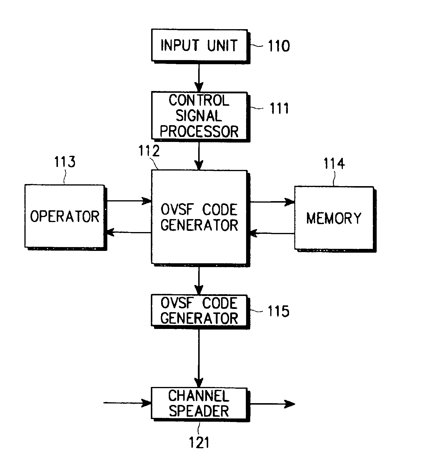
[0028]It is another object of the present invention to provide an apparatus and method for efficiently managing the limited OVSF code resources in a CDMA communication system.
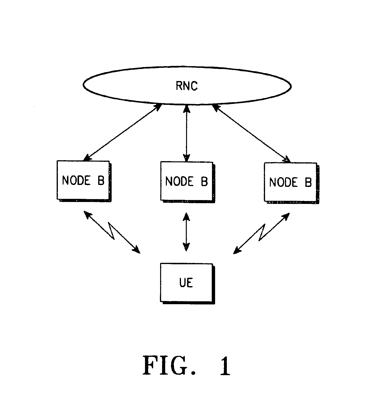
[0030]It is yet another object of the present invention to provide an apparatus and method for enabling a UTRAN to efficiently allocate a channel to a user equipment (UE) in a CDMA communication system.

Problems solved by technology

Therefore, it is not possible to simultaneously allocate the child nodes of the allocated specific node to the data part.
The conventional OVSF code allocation method has a limitation on use of the OVSF code, since when one child node connected to a specific mother node is allocated to the data part, the remaining one child node is allocated to the control part.
As a result, the channel allocation resources run short.

Method used


Image

  • Apparatus and method for allocating channel using OVSF code for uplink synchronous transmission scheme in a W-CDMA communication system
  • Apparatus and method for allocating channel using OVSF code for uplink synchronous transmission scheme in a W-CDMA communication system
  • Apparatus and method for allocating channel using OVSF code for uplink synchronous transmission scheme in a W-CDMA communication system

Examples


first embodiment

[0060

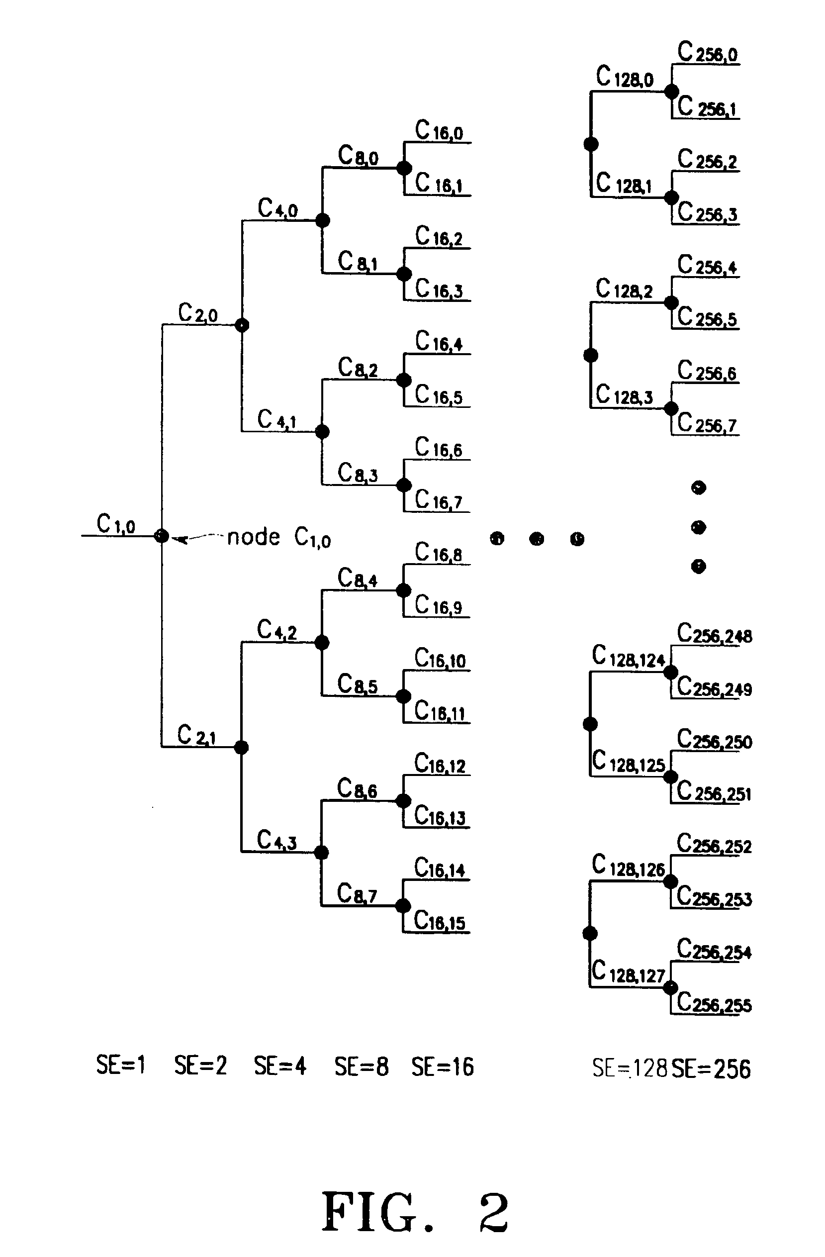
[0061]First, a sub-tree of a C4,3 node which is one of the nodes with SF=4 is allocated to the control part. Although the C4,3 node is allocated to the control part in the following description, it is also possible to selectively allocate one of the nodes C4,0, C4,1 and C4,2 other than the node C4,3 out of the SF=4 nodes to the control part. Since the nodes existing in the sub-tree of the C4,3 node are allocated to the control part, they are not allocated for the data part. Instead, the 12 SF=64 nodes C64,52, C64,53, C64,54, . . . , C64,63 are defined as nodes for the control part (or control part nodes). A definition of one-to-one mapping between the control part nodes C64,52, C64,53, C64,54, . . . , C64,63 and SF=16 data part nodes C16,0, C16,1, C16,2, . . . , C16,11 will be given. Here, the node mapping is performed using a mapping function F1(Cdata,16,k)=Ccontrol,64,63−k (0≦k≦11), where Cdata,16,k denotes node C16,k for the data part and Ccontrol,64,63−k denotes a node C64,...

second embodiment

[0080

[0081]The second embodiment is considered for the case where SF=256 is allocated for the control part, and SF=4, SF=8, SF=16, SF=32, SF=64, SF=128 and SF=256 are allocable for the data part. Here, even when SF=32, SF=64, SF=128 and SF=256 can be allocated for the data part as in the RACH (Random Access Channel), it is possible to use the mapping rule for the data part and the control part by using the following rule. As in the first embodiment where SF for the control part is 64, even when SF for the control part is 256, a sub-tree of any one of SF=4 nodes is used for the control part. For convenience, this node will be assumed to be C4,4. A normal mapping rule for the 48 SF=64 nodes and 48 SF=256 nodes for the data part is defined as follows.

[0082]

F5(Cdata,64,k)=Ccontrol,256,255−k

[0083]According to Rule 5, Cdata,64,k nodes for the data part are allocated to Ccontrol,256,256−k nodes for the control part as shown in Table 4 below.

[0084]

TABLE 4Data PartControl PartSF = 4SF = 8SF ...

third embodiment

[0113

[0114]Next, a third embodiment of the present invention will be described. Since the UEs using the USTS (Uplink Synchronous Transmission Scheme) has a property of a low mobility, it is possible to limit the spreading factor (SF) to a specific value. Accordingly, in this embodiment, it is assumed that SF of the DPDCH (i.e., SF of the data part) in the UE employing one USTS is fixed to one value.

[0115]In this embodiment, SF=256 is allocated for the DPDCH (or control part) and one of SF=4, SF=8, SF=16, SF=32, SF=64, SF=128 and SF=256 is variably allocated for the DPDCH (or data part). First, the DPDCH defines mapping from the frontmost end in the OVSF tree architecture out of the nodes with the set SF, and then, the DPCCH defines mapping from the rearmost end in the OVSF tree architecture out of the SF=256 nodes. That is, a mapping function of F11(Cdata,SF,k)=Ccontrol,256,255−k(0≦k≦11) is used. In this case, it is possible to know the maximum number of the allocable nodes in one O...


PUM


Abstract

Disclosed is a channel allocation method in a CDMA communication system. The method comprises receiving from a UTRAN one SF node CSF,k out of 2m−1 SF nodes (where m is an integer larger than 3) arranged in the form of a tree having a mother node and child nodes; searching a group including the received SF node CSF,k in accordance with Formula (1) below; spreading a signal on a dedicated physical data channel (DPDCH) with an OVSF code corresponding to a selected one of the received SF node and its child nodes in the searched group; and spreading a signal on a dedicated physical control channel (DPCCH) with an OVSF code corresponding to an SF node determined by Formula (2) below based on the received SF node. For⁢ ⁢SF≤2m-14,(P1·SF,P1·k)=(2m-14,n)⁢⁢For⁢ ⁢SF>2m-14,(P2·2m-14,P2·n)=(SF,k)⁢⁢where,P1=2m-14·SF⁢ ⁢and⁢ ⁢P2=4·SF2m-1.Formula (1)F⁡(C2m-14·k)=C2m-1⁢2m-1-k-1⁢ ⁢(k=0,1,…⁢ )⁢⁢F⁡(C2m-14·k)=C2m-1,2m-1-(k-32)⁢ ⁢(k=0,1,…⁢ ).Formula  (2)

Description

PRIORITY[0001]This application claims priority to application entitled “Apparatus and Method for Allocating OVSF Codes in W-CDMA Communication System” filed in the Korean Industrial Property Office on Jan. 17, 2000 assigned Serial No. 2000-2076; an appplication entitled “Apparatus and Method for Efficiently Allocating Given Radio Resource in CDMA Communication System” filed in the Korean Industrial Property Office on Jan. 18, 2000 and assigned Serial No. 2000-2161; an application entitled “Appatatus and Method for Efficiently Allocating Given Radio Resource in a CDMA Communication System” filed in the Korean Industrial Property Office on Jan 19, 2000 and assigned Serial No. 2000-2503; an application entitled “Appaaratus and Method for Allocating OVSF Codes for Uplink Synchronous Transmission Scheme in a W-CDMA Communication System” filed in the Korean Industrial Property Office on Jun. 24, 2000 and assigned Serial No. 2000-35173; an application entitled “Apparatus and Method for All...

Claims


Application Information

Patent Timeline
IPC IPC(8): H04J11/00H04J13/04H04J13/00H04J13/20
CPCH04J13/20H04J13/0044
Inventor CHOI, SUNG-HOPARK, CHANG-SOOKIM, JAE-YOELPARK, SEONG-IIIJUNG, KI-HOCHOI, HO-KYULEE, HYUN-WOOKWAK, YONG-JUNLEE, KOOK-HEUI
Owner SAMSUNG ELECTRONICS CO LTD
Learn More