Reference fixture for roundness measuring instrument

a reference fixture and measurement instrument technology, applied in the direction of instruments, mechanical roughness/irregularity measurements, electrical/magnetic diameter measurements, etc., can solve the problems of inability to acquire data from the face, long calculation process, and inability to measure the bottom face of the origin ball, etc., to improve the efficiency of measuring and improve the accuracy of measuring

Active Publication Date: 2005-05-03
MITUTOYO CORP
View PDF12 Cites 31 Cited by
  • Summary
  • Abstract
  • Description
  • Claims
  • Application Information

AI Technical Summary

Benefits of technology

[0013]An object of the present invention is to provide a reference fixture for a roundness measuring instrument that eliminates the need for a large calculation program or the like, enables to continuously perform acquisition of origin information of the roundness measuring instrument and sensitivity adjustment of a detector thereof and enhances a measuring efficiency and measuring accuracy.
[0015]With this arrangement, the origin information of the roundness measuring instrument can be acquired since the reference fixture for the roundness measuring instrument is set on the workpiece rotary mechanism and the sensor of the detector of the roundness measuring instrument is related to the reference ball by contacting etc. whereas the sensitivity of the detector can be calibrated since the sensor of the detector is involved with the calibration master. Thus, it is not necessary to replace the reference ball and the calibration master at each time when the operator acquires the origin information or calibrates the sensitivity. Since the holder is formed in a shape capable of measuring the reference ball by the detector in the axial direction and the direction orthogonal to the axial direction of the calibration master, the detector can scan the surface of the reference ball in Z-axis direction or X-axis direction so as to detect the maximum point or the minimum point on the spherical surface as the origin information. Even when the position of the detector is changed, the origin information can be acquired in every position, thus easily acquiring the compensation value for the position of the detector along with the position change. Particularly, because the bottom face of the reference ball can be also scanned, the compensation value can be easily acquired corresponding to various positions of the detector.
[0016]Consequently, a large calculation program or the like is not necessary so that the acquisition for the origin information of the roundness measuring instrument and the sensitivity adjustment of the detector can be continuously performed, thus enhancing the measuring efficiency and the measuring accuracy.
[0018]With this arrangement, since the interference between the holder and the detector can be minimized in various positions of the detector, the origin information can be acquired in various positions of the detector.
[0021]When the reference ball is damaged etc., the inclined part may be removed from the shank to be replaced with new one, thus facilitating the manufacturing procedures as compared to that the origin ball is integrally formed with the shank and the inclined part.
[0023]With this arrangement, the sensitivity of the detector can be easily calibrated based on the result in which the roundness of the lateral periphery of the calibration master including the flat part is measured by the detector.

Problems solved by technology

At the origin setting according to the above publication, since a calculation process on the basis of the form analysis is complicated, the calculation process takes a long time whereas a large calculation program needs to be built.
In the second method, since the shank holding the origin ball is perpendicularly provided on the workpiece rotary mechanism, the orientation of the detector becomes upward, thus being impossible to measure a bottom face of the origin ball.
Therefore, data cannot be acquired from the face unavailable for the measurement, thereby impossible to acquire highly accurate origin information.
Thus, since the origin ball and the calibration master need to be replaced, the preparation takes a long time and is inconvenient in use.
When the origin ball and the calibration master are replaced, since the operator touches the calibration master by hand, an affection on the calibration master due to body temperature of the operator may be the bottleneck in improvement of measuring accuracy.

Method used


Image

  • Reference fixture for roundness measuring instrument
  • Reference fixture for roundness measuring instrument
  • Reference fixture for roundness measuring instrument

Examples


Embodiment Construction

)

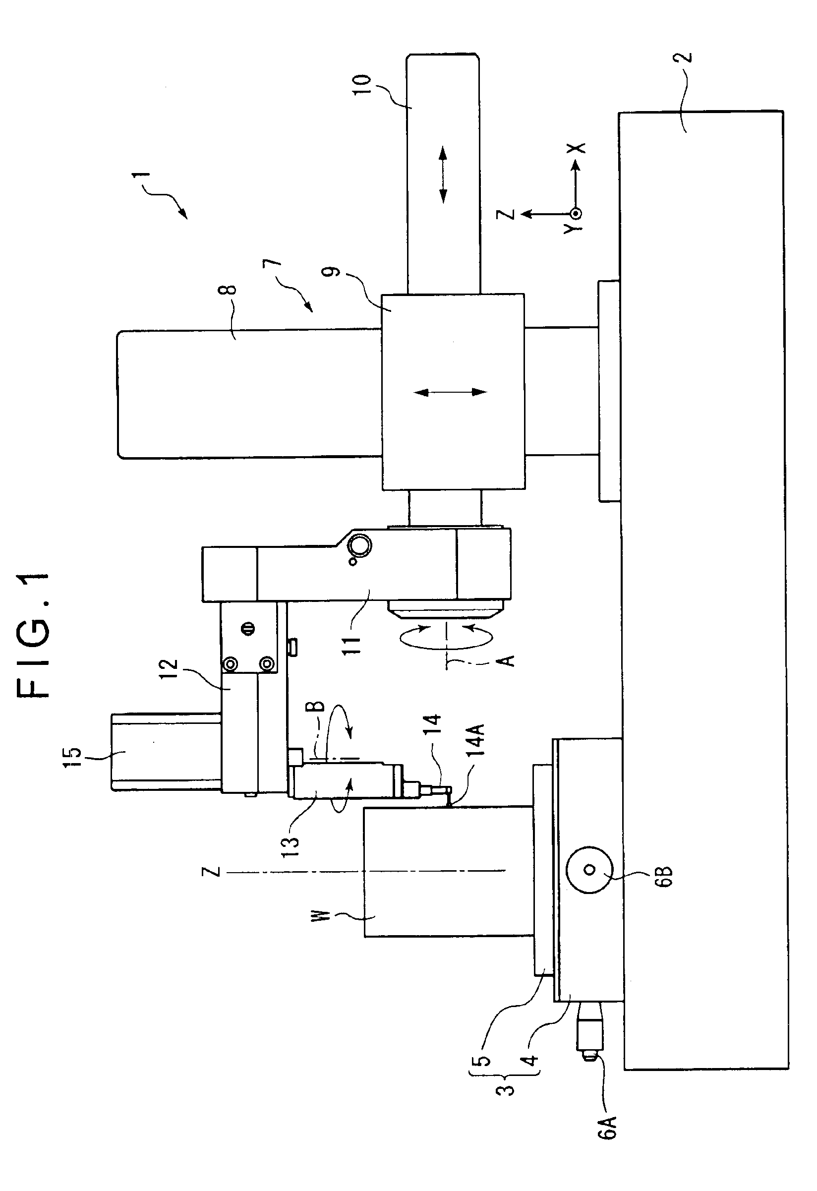
[0040]An embodiment of the present invention will be described with reference to attached drawings.

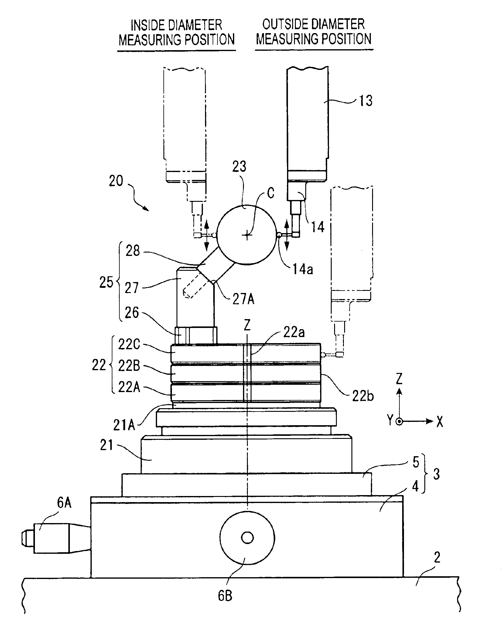
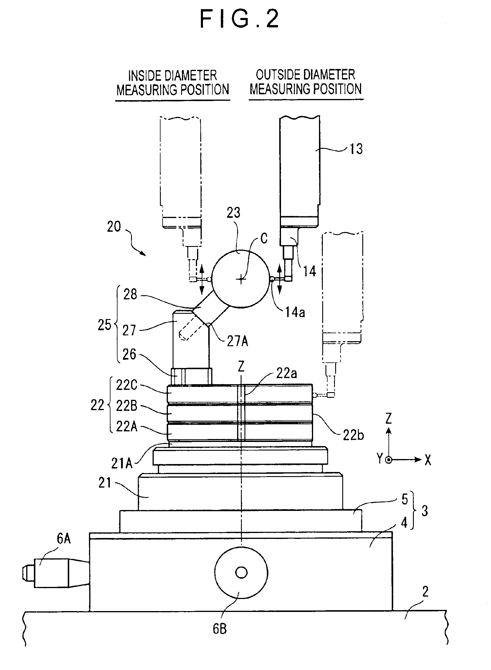
[0041]FIG. 1 shows a roundness measuring instrument 1 in which a reference fixture 20 for the roundness measuring instrument (hereafter simply referred to as a reference fixture) shown in FIG. 2 and the following drawings according to the present invention.

[0042]The roundness measuring instrument 1 includes a base 2, a workpiece rotary mechanism 3 disposed on a top face of the base 2 and closer to a side thereof to rotate a workpiece W as an object to be measured and a position detecting mechanism 7 disposed on the top face of the base 2 and closer to the other side thereof to detect a position of the workpiece W on a external surface thereof.

[0043]The workpiece rotary mechanism 3 has a turntable 4 rotatably provided on the base 2 via a rotation driver mechanism (not shown) and an XY table 5 where the workpiece W is set on a top face of the turntable 4. The turntable 4 is provided wit...


PUM


Abstract

A reference fixture (20) for a roundness measuring instrument performs acquisition of origin information of a roundness measuring instrument (1) including a workpiece rotary mechanism (3) on which a workpiece is set and a probe (14) provided with a stylus (14a) and also performs calibration of the probe (14). The reference fixture (20) includes a mount (21), a calibration master (22) provided on a top face of the mount (21) for calibrating the sensitivity of the probe (14), an origin ball (23) disposed above the calibration master (22) for providing the origin information of the roundness measuring instrument (1) by the stylus (14a) of the probe (14), and a holder (25) that holds the origin ball (23).

Description

BACKGROUND OF THE INVENTION[0001]1. Field of the Invention[0002]The present invention relates to a reference fixture for a roundness measuring instrument, particularly, the one that can acquire origin information of the roundness measuring instrument and calibrate a detector thereof.[0003]2. Description of Related Art[0004]Conventionally, a roundness measuring instrument, which is one type of form measuring instrument, have been used as a measuring instrument that measure geometrical deviation such as roundness, flatness and parallelism of an object to be measured.[0005]Such roundness measuring instrument has a detector provided with a sensor at a distal end of a lever capable of swinging in a direction orthogonal to the surface of a workpiece, or the object to be measured. A measurement data is acquired by the detector scanning along the surface of the workpiece with the sensor contacting the surface of the workpiece and collecting the data so as to measure roundness, cylindricity,...

Claims


Application Information

Patent Timeline
Patent Type & Authority Patents(United States)
IPC IPC(8): G01B5/004G01B21/30G01B5/28G01C25/00G01B7/28G01B7/00G01B5/20
CPCG01B7/282G01B7/12
Inventor SAKATA, YUKIHIROOOMORI, YOSHIYUKISHINDO, HIDEKINOGUCHI, KAZUSHI
Owner MITUTOYO CORP
Why Eureka
Try Eureka