
Insect trap

a technology for insect traps and traps, applied in insect traps, electrical equipment, animal husbandry, etc., can solve the problems of insect traps which require permanent or semi-permanent installation, insect traps that are not as well suited for seasonal or intermittent use, and the adhesive characteristics of sticky substances are usually diminished, so as to improve the appearance and easy replacement of sheet materials. , the effect of easy mounting and removal

Inactive Publication Date: 2005-05-03
GARDNER MFG CO INC
View PDF136 Cites 88 Cited by
  • Summary
  • Abstract
  • Description
  • Claims
  • Application Information

AI Technical Summary

Benefits of technology

"The present invention is about an insect trap that can be easily mounted and removed, making it suitable for intermittent, seasonal, or temporary use. The insect trap has an improved appearance compared to other insect traps and is more effective. It includes an enclosure with an insect attractant, a neutralizer, and an electrical plug. The enclosure can also have additional features such as a timer, light detector, thermocouple, or motion detector to enhance the effectiveness or appearance of the insect trap. The technical effects of the invention are improved ease of use, effectiveness, and appearance."

Problems solved by technology

One disadvantage associated with insect traps of this type is that the adhesive characteristics of the sticky substance usually diminish over time.
Also, such insect traps usually become unsightly due to the concentration of dead insects on the sticky substance.
Insect traps which require permanent or semi-permanent installation are not as well suited for seasonal or intermittent use as an insect trap which can be easily installed when needed and easily removed when not needed.
Further, insect traps which require permanent or semi-permanent installation may require alteration of walls onto which they are mounted, making such insect traps unsuitable for temporary use, for example when used in a public shelter house or in a space which is rented for a short period of time.
However, the unsightly appearance of dead insects in such traps diminishes the usefulness of such traps, especially in spaces used for dining or entertaining, for example in restaurants, reception halls, and the like.
Further, such traps may be less effective than traps which use electrical power.

Method used


Image

  • Insect trap
  • Insect trap
  • Insect trap

Examples


Embodiment Construction

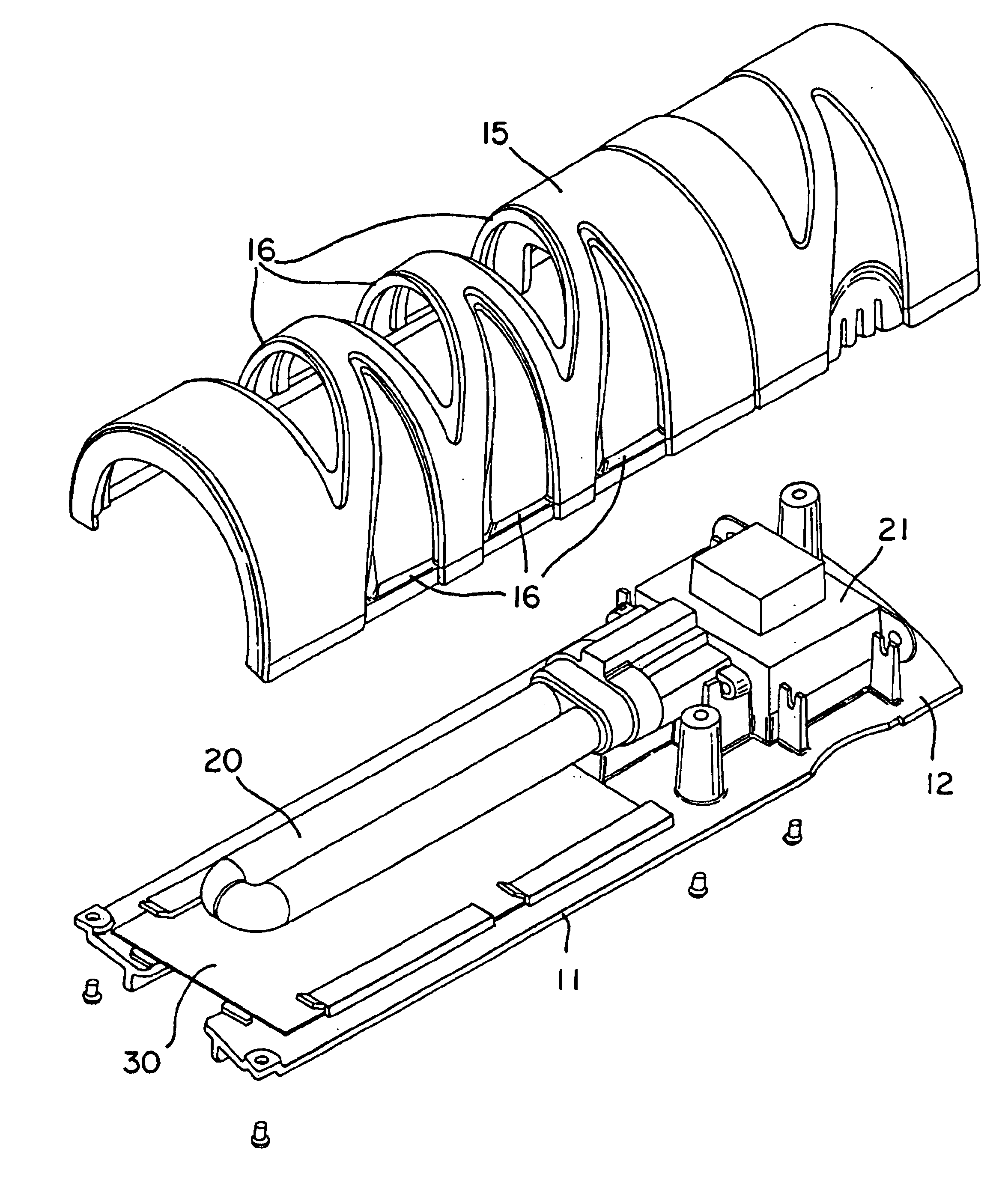
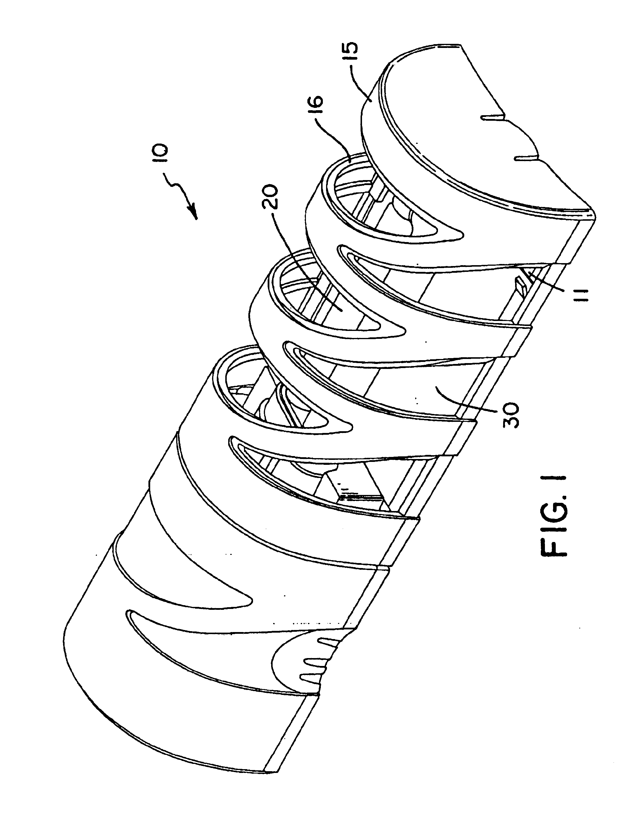
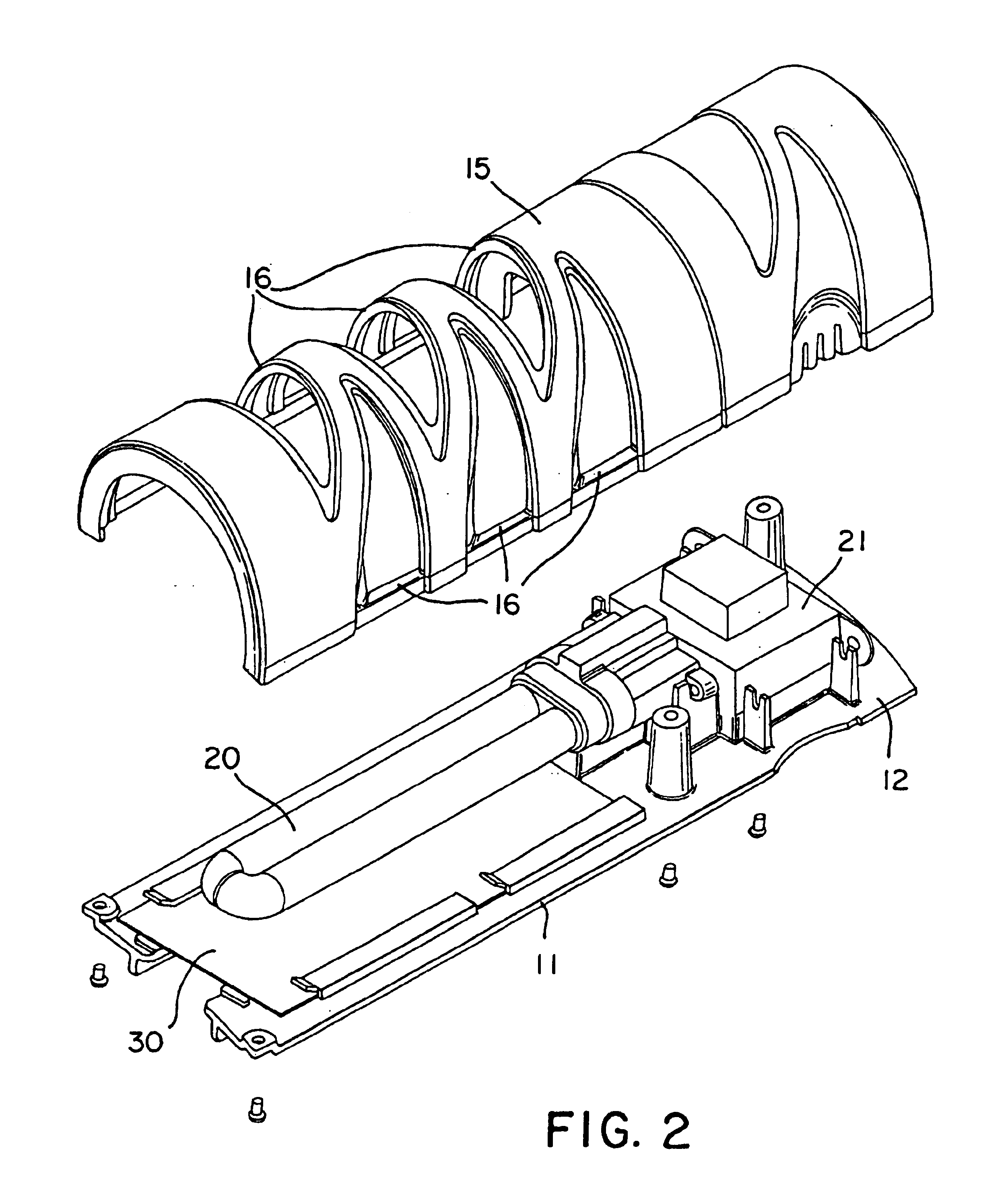
[0021]With reference to the drawings, FIG. 1 shows a perspective view of a preferred embodiment of an insect trap according to the invention, indicated generally at 10. The insect trap 10 includes a base 11 and a housing 15 having at least one opening 16. The base 11 and housing 15 together form an enclosure having at least one opening 16, although this is not required and a suitable enclosure having at least one opening may be formed in other ways.

[0022]The insect trap 10 includes an insect attractant which is preferably a light 20, although this is not required and other insect attractants may be used. The insect trap 10 also includes an insect neutralizer which is preferably an adhesive surface 30, although this is not required and other insect neutralizers may be used. In the insect trap 10, the opening 16 allows light to pass out of the enclosure in order to attract insects. In the insect trap 10, the opening 16 also allows insects to enter the enclosure where they may be ensna...


PUM


Abstract

An insect trap which includes a base having a rear surface and a front surface, a housing mounted to cover at least a portion of the front surface of the base, an insect attractant such as a light located at least partially within the housing, an insect neutralizer such as an adhesive surface located at least partially within the housing, and an electrical plug protruding from the rear surface of the base whereby the insect trap may be mounted to an electrical socket by inserting the electrical plug into the electrical socket. The insect trap can be easily mounted and removed, making it suitable for intermittent, seasonal, or temporary use.

Description

FIELD OF THE INVENTION[0001]The present invention relates generally to the field of insect traps, and particularly to insect traps which include an insect-attracting light source.BACKGROUND OF THE INVENTION[0002]Insect traps that include a sticky substance capable of ensnaring insects are well known. Such insect traps, for example fly paper, may include a sticky substance applied as a coating on paper or other sheet material. One disadvantage associated with insect traps of this type is that the adhesive characteristics of the sticky substance usually diminish over time. Also, such insect traps usually become unsightly due to the concentration of dead insects on the sticky substance. Thus, insect traps of this type require periodic maintenance, by replacing the insect trap entirely or by replacing the portion of the insect trap that bears the sticky substance.[0003]Insect traps that include an insect attractant, for example a light, are also known. Examples of such traps are disclos...

Claims


Application Information

Patent Timeline
Patent Type & Authority Patents(United States)
IPC IPC(8): A01M1/02A01M1/00A01M1/14
CPCA01M1/026A01M1/145A01M2200/012
Inventor STUDER, BRUCEJONES, TIM
Owner GARDNER MFG CO INC
Learn More