
Modular deck drainage system

a drainage system and module technology, applied in roof drainage, balconies, walls, etc., can solve the problems of high installation cost, difficult and time-consuming systems, and inability to fully utilize the area below the deck

Inactive Publication Date: 2005-05-03
JACKSON ANSLEM
View PDF10 Cites 19 Cited by
  • Summary
  • Abstract
  • Description
  • Claims
  • Application Information

AI Technical Summary

Benefits of technology

[0012]It is another object to provide a deck drainage system which can be installed beneath virtually any deck and does not require any customization.

Problems solved by technology

As outdoor decks have become more popular, efforts to fully utilize the area below the decks have generally been limited as the floor boards and joists of a typically constructed deck allow water to drip through and onto the area beneath the deck.
While these systems are generally effective, they suffer from two major drawbacks.
First, the systems are difficult and time consuming to install, often requiring custom built drainage sections.
Second, the systems are expensive.
While this system does conserve some “headroom” it suffers from the drawback in that one drainage panel is required for every two floor joists, which substantially increases installation time.
Also, improper construction will result in leakage between the side of the joist and the edge of the drainage panel.
This system suffers from the drawback that the gutters must be manufactured at one site and then transported to the installation site.
Once installed, Thibodeau's drainage system may not be removed without extensive destruction of the deck.

Method used


Image

  • Modular deck drainage system
  • Modular deck drainage system
  • Modular deck drainage system

Examples


Embodiment Construction

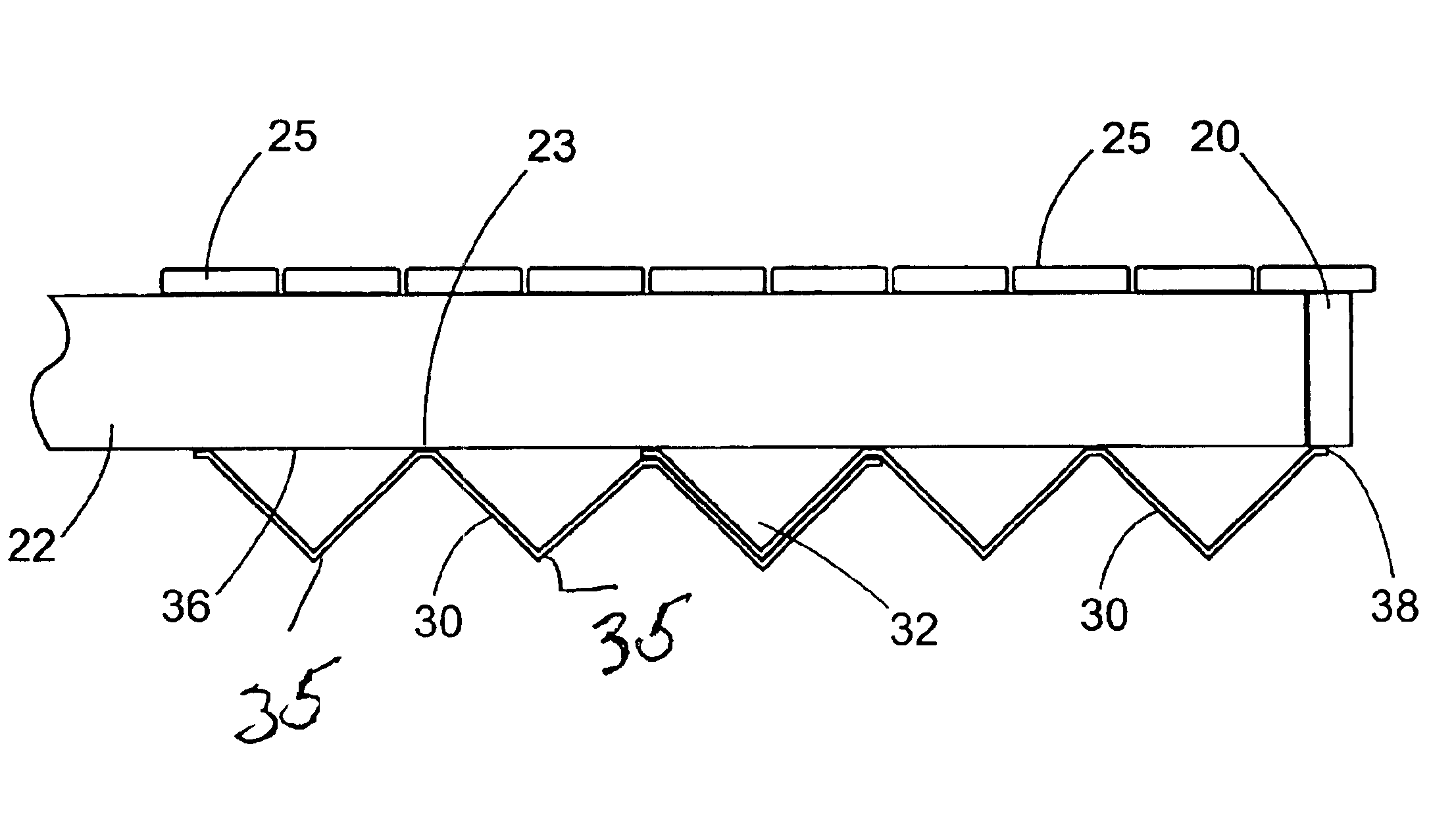
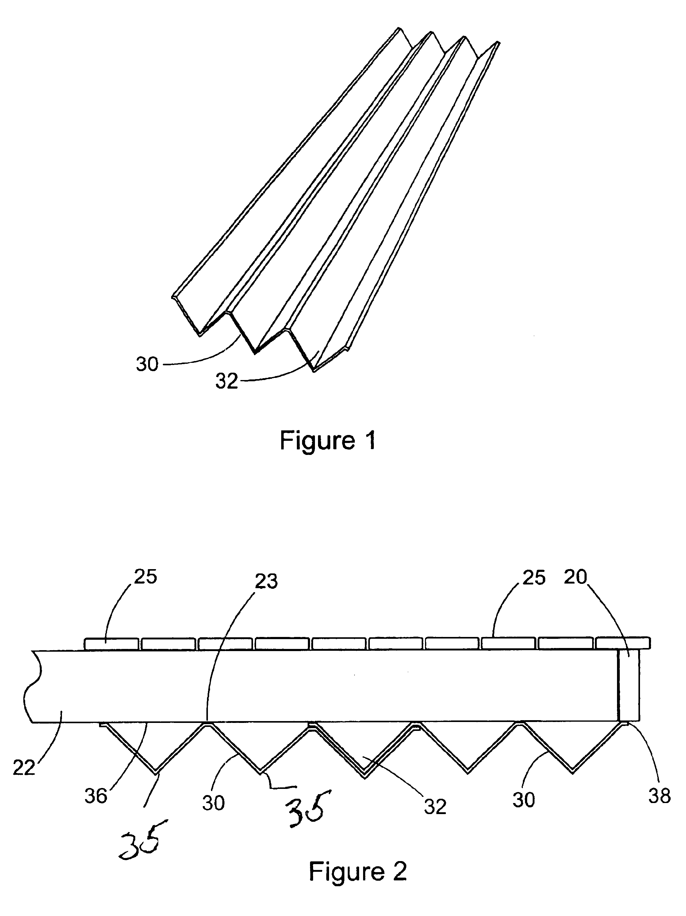
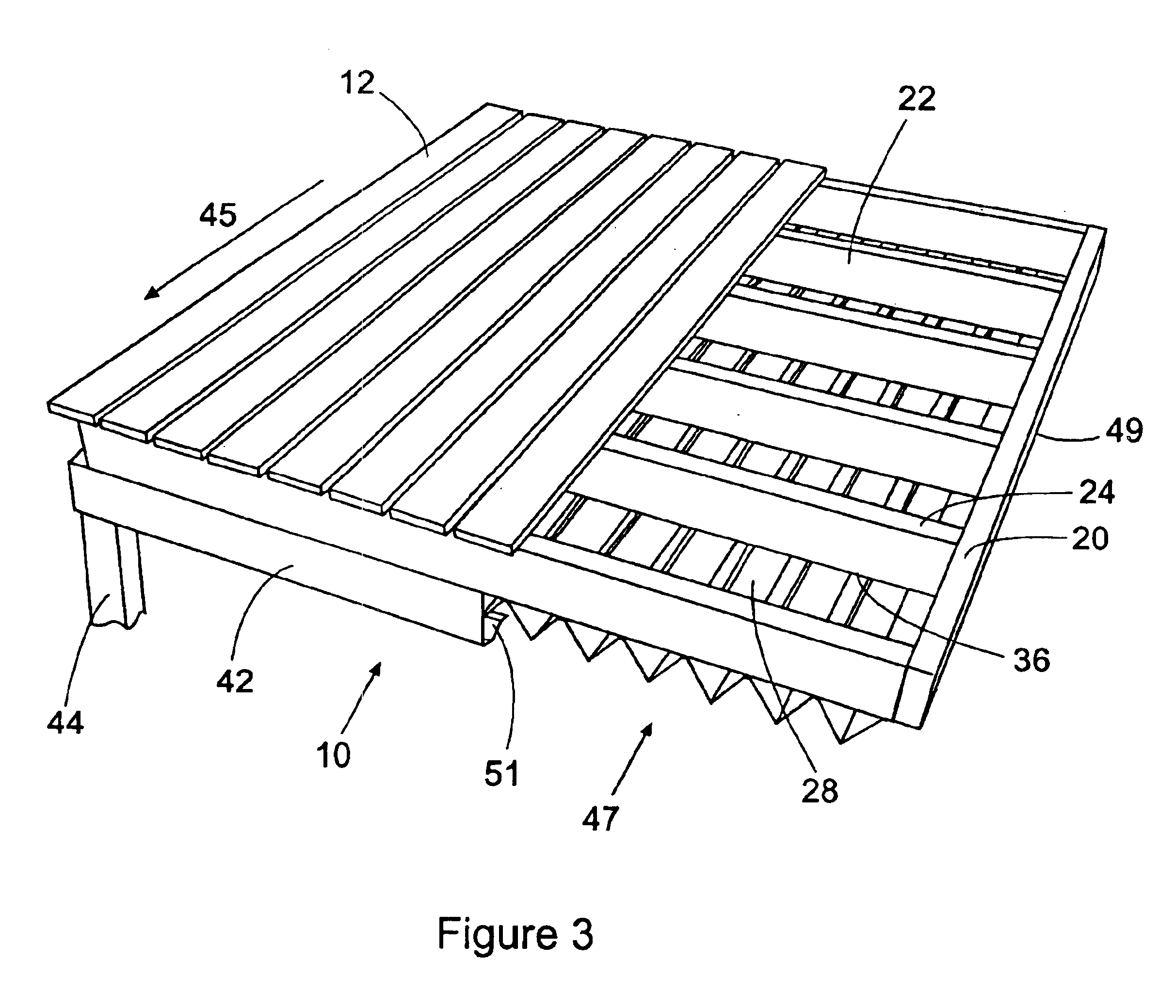
[0023]Referring now to FIGS. 1-5, the modular deck drainage system of the present invention, generally indicated by the numeral 10, is shown in position on a deck 12. FIG. 3 depicts a typical deck construction having a main support frame comprising four support beams 20 arranged in a rectangular configuration and connected at their ends. The deck 12 is raised, relative to the ground, by connecting the frame to additional support members (not shown), the additional support members connected to a primary structure such as a house. A plurality of elongated, parallel, generally rectangular deck joists 22 are connected between the support beams 20 at regularly spaced intervals.

[0024]Transversely disposed across the top edges 24 of the joists 22, in spaced relation so as to provide a series of parallel drainage cracks, are a plurality of floor boards 25. The drainage cracks allow water to drain from the floor boards to prevent undesirable pooling of water on the deck 12, and to minimize t...


PUM


Abstract

A deck drainage system having a plurality of channeled drainage panels. The drainage panels are mounted to direct water flow transversely of the deck joists to a gutter, the panels connected to and suspended from the underside of the joists. The gutter is mounted transversely across the discharge ends of the drainage panels to collect water therefrom and direct it to a down spout. Drainage panels, which are rectangular with the individual drainage channels extending lengthwise, may be overlapped both lengthwise and widthwise to fit the perimeter of the deck.

Description

BACKGROUND OF THE INVENTION[0001]1. Field of the Invention[0002]The present invention concerns drainage systems. More particularly, the invention is directed to a drainage system specifically designed to drain water dripping between floor boards of outdoor decks.[0003]2. Description of the Prior Art[0004]As outdoor decks have become more popular, efforts to fully utilize the area below the decks have generally been limited as the floor boards and joists of a typically constructed deck allow water to drip through and onto the area beneath the deck. Accordingly, deck drainage systems have been devised to capture and channel water away from the area below the deck. While these systems are generally effective, they suffer from two major drawbacks. First, the systems are difficult and time consuming to install, often requiring custom built drainage sections. Second, the systems are expensive.[0005]U.S. Pat. No. 6,260,316 issued to Davis, et al. discloses one such drainage system. The sys...

Claims


Application Information

Patent Timeline
IPC IPC(8): E04B1/00E04F17/00E04D13/04
CPCE04B1/003E04F17/00E04D13/0477
Inventor JACKSON, ANSLEM
Owner JACKSON ANSLEM
Learn More