
Method of providing temperature controlled air and an apparatus usable for this

a technology of temperature control air and temperature control, which is applied in the direction of domestic cooling apparatus, lighting and heating apparatus, cooling fluid circulation, etc., can solve the problems of complex and/or expensive multi-zone supply modules, inability to meet the needs of most application areas, and inability to meet the needs of multi-zone supply, etc., to achieve the effect of simple means

Inactive Publication Date: 2005-05-03
MAHLE INT GMBH
View PDF15 Cites 26 Cited by
  • Summary
  • Abstract
  • Description
  • Claims
  • Application Information

AI Technical Summary

Benefits of technology

[0005]It is therefore the object underlying the present invention to make available a method to make available temperature controlled air for a first region and a second region in a vehicle which can be carried out with simple means as well as to provide a suitable simple supply apparatus to carry out the method to make available cold air and hot air.
[0021]To obtain a supply apparatus in accordance with the invention to be installed as simply as possible into a vehicle, it is preferred for the auxiliary blower to be arranged together with the cold air source and the hot air source in a common housing. In particular a housing with a modular design is also understood by this in which a housing of the auxiliary blower is connected to a housing of the cold air source and of the hot air source. Such a spatial combination does not only have the advantage that only one part has to be installed on the installation of the supply apparatus in accordance with the invention into a motor vehicle, but furthermore that the making available of the electrical connections required when an electrical drive is used for the auxiliary blower is also greatly simplified since these can be combined with the electrical connections of the cold air source and of the hot air source.
[0024]Any kind of device can serve as the heating device, by means of which air supplied to it can be heated to a higher temperature. It can here be a heating which is operated electrically or by fuel independent of a drive device, in particular of a combustion engine, of the vehicle. However, preferably a heating core is used to which a liquid, for example a coolant, heated on the operation of the drive device of the vehicle, in particular of a combustion engine, can be supplied to heat an air flow passing through it or flowing past it. Since the total supplied air is first cooled and then partly heated again, the moisture content of the air made available is clearly reduced such that in particular a removal of moisture on fogged windows and a drying of the passenger compartment in wet weather can take place faster.
[0025]It is preferred, to support a uniform supply of the two regions with hot air, for the heating device and the auxiliary blower to be arranged directly adjoining one another such that a part flow of a hot air flow made available by the heating device can be sucked in transversely to the flow direction of the remaining hot air flow of the auxiliary blower. A uniform branching of the part flow thus results over a large part of a discharge surface of the heating device which largely prevents the occurrence of excessively hot or cold regions at the discharge surface.
[0027]In the method in accordance with the invention, it is preferred for the second cold air part flow transported with the help of the auxiliary blower and for the second hot air part flow transported with the help of the auxiliary blower each to be split into further cold air part flows or hot air part flows respectively and for a corresponding further cold air part flow and a corresponding further hot air part flow to be mixed to make available temperature controlled air for different zones in the second region. In the air conditioning system in accordance with the invention, it is preferred for this purpose for at least one connection passage for cold air, and a corresponding connection passage for hot air, in particular in each case for the second region, to be branched at least once and for respective metering / and or mixing devices to be arranged in or at the corresponding branches for cold air or hot air respectively. In this further development of the invention, the large advantage results that different zones can be supplied in the second region with respectively individually temperature controlled air flows, optionally of individual strength, without additional connection passages having to be led from the cold air source and hot air source or from the auxiliary blower into the second region. A strengthening of temperature controlled air flows for a plurality of zones in the second region can take place simply in particular with only one auxiliary blower.

Problems solved by technology

Such multi-zone supply modules are, however, very complex and / or expensive.
The technical complexity associated with this and the cost associated with this are, however, not tolerable for most application areas.

Method used


Image

  • Method of providing temperature controlled air and an apparatus usable for this
  • Method of providing temperature controlled air and an apparatus usable for this

Examples


Embodiment Construction

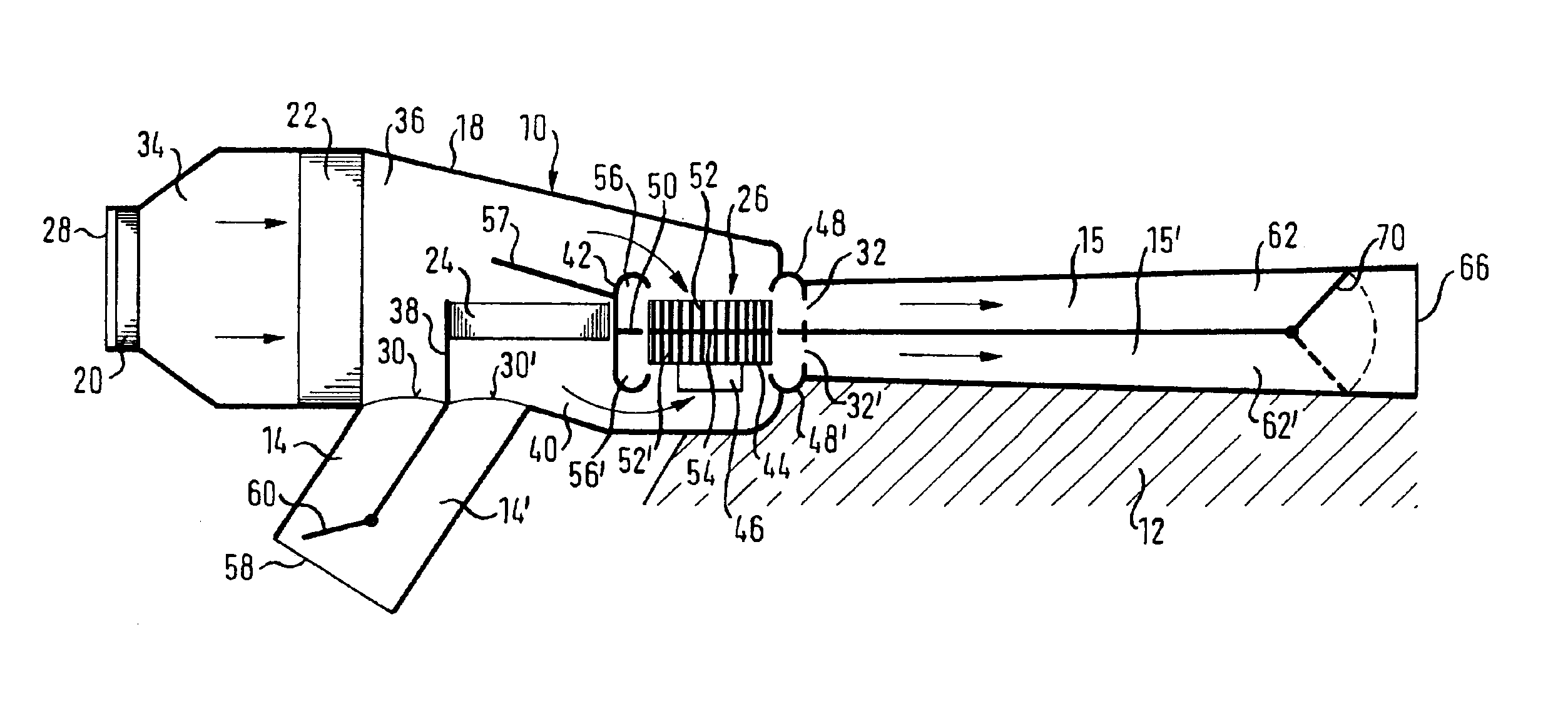
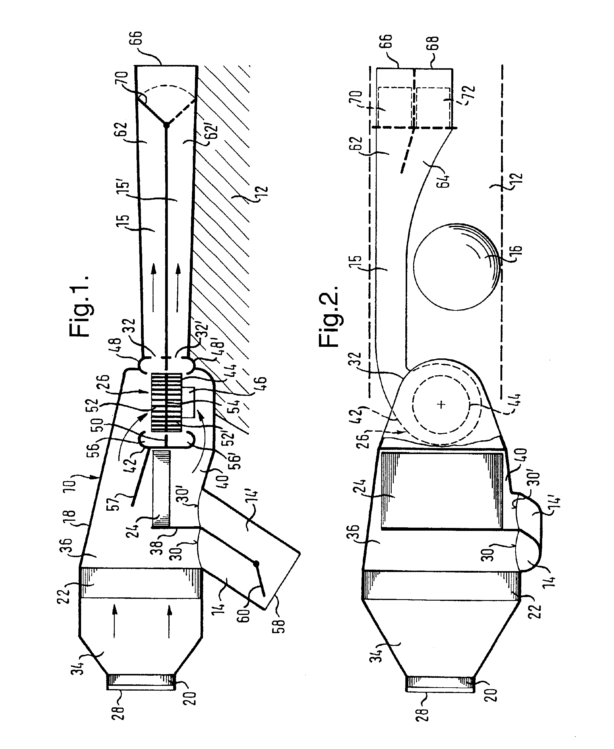
[0033]In FIGS. 1 and 2, a vehicle air conditioning system in a motor vehicle shown only sectionally, has a supply apparatus 10 which is arranged in part on a transmission tunnel 12 in the front region of the motor vehicle. First front connection passages 14 and 14′ for cold air and hot air respectively for the front region of the motor vehicle and two rear connection passages 15 and 15′ for cold air and hot air respectively for a backseat area of the motor vehicle are connected to the supply apparatus 10, with the rear connection passages 15 and 15′ leading from the supply apparatus 10 past a gear stick 16 on the transmission tunnel 12 into the backseat region.

[0034]The supply apparatus 10 has a housing 18 in which—only shown schematically in the Figures—there are arranged a main blower 20, an evaporator 22, a heating core 24 and an auxiliary blower 26.

[0035]The housing 18 has an air inlet 28, first cold air outlets and hot air outlets 30 and 30′ and second cold air outlets and hot ...


PUM


Abstract

In a method of making available temperature controlled air for a first region and a second region in a vehicle, a cold air flow and a hot air flow are generated. At least one first cold air part flow and one first hot air part flow respectively are formed from the cold air flow and from the hot air flow and the first cold air part flow and the first hot air part flow are mixed to form a first temperature controlled part flow for the first region. Furthermore at least one second cold air part flow and one second hot air part flow respectively are formed from the cold air flow and the hot air flow and the second cold air part flow and the second hot air part flow are transported separately by means of an auxiliary blower and are mixed downstream of the auxiliary blower to form a second temperature controlled part flow for the second region.

Description

TECHNICAL FIELD[0001]The present invention relates to a method of providing temperature controlled air for a first and a second region in a vehicle as well as to a supply apparatus to make available cold air and hot air for a vehicle air conditioning system.BACKGROUND OF THE INVENTION[0002]In many vehicles, an air conditioning system is provided to increase comfort by means of which an interior space of a passenger compartment of the vehicle can be air conditioned by supplying suitably temperature controlled air. For this purpose, the vehicle air conditioning system has a supply apparatus to make available cold air and hot air. Cold air flows and hot air flows made available by the supply apparatus are mixed to form a corresponding flow of temperature controlled air in accordance with a predetermined desired temperature and supplied to the passenger compartment.[0003]To increase the comfort, it is desirable for different zones of the passenger compartment to be individually temperat...

Claims


Application Information

Patent Timeline
Patent Type & Authority Patents(United States)
IPC IPC(8): B60H1/00
CPCB60H1/00064B60H2001/002B60H2001/00107B60H2001/00099
Inventor PETESCH, JEAN-CLAUDEVAN HAUTEN, HARTMUT E
Owner MAHLE INT GMBH
Learn More