[0006]The task of the invention is to make available an actuating device of the type described above which allows an authorized user to activate conveniently the securing function via the central locking unit, but which at the same time gives him the ability to allow unauthorized users access only to selected areas. Another task of the invention is to design the actuating device in such a way that, even if excessive force is applied to the actuating element, there is no danger that the lock can be opened without
authorization. Attempts to open the lock improperly are to be prevented more reliably, and the absolute distances by which the lock is adjusted or turned are to give the user the impression of a precision mechanism.
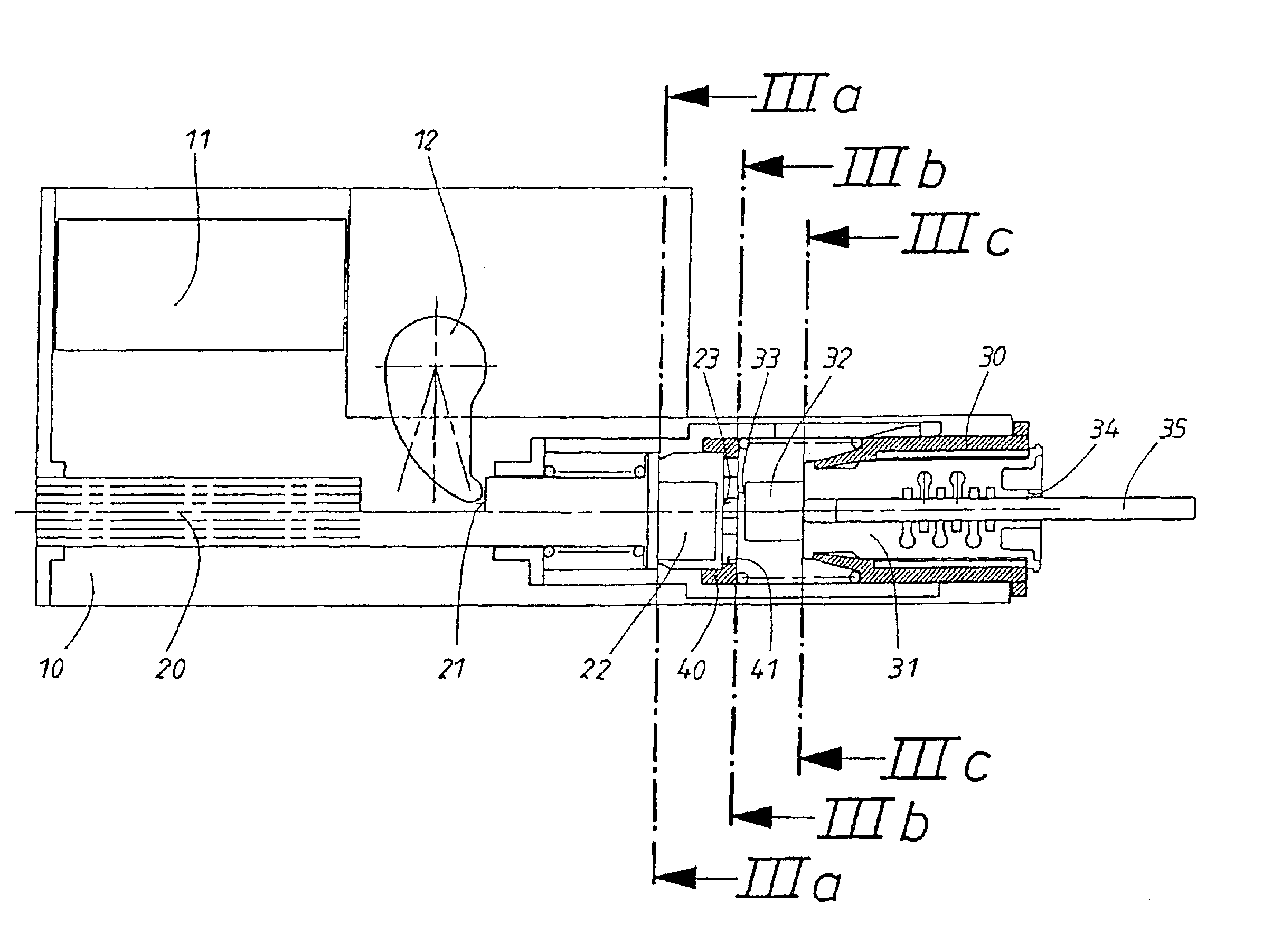
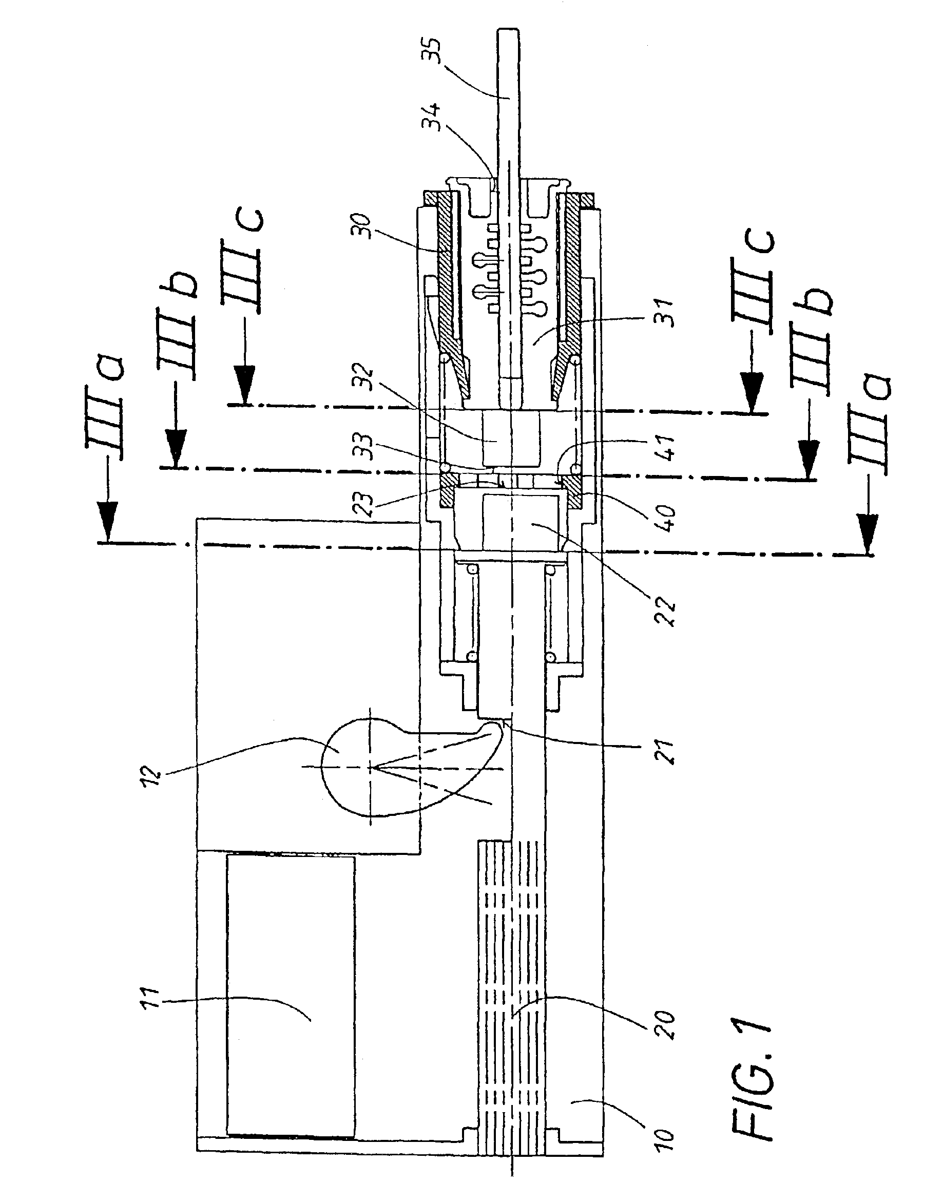
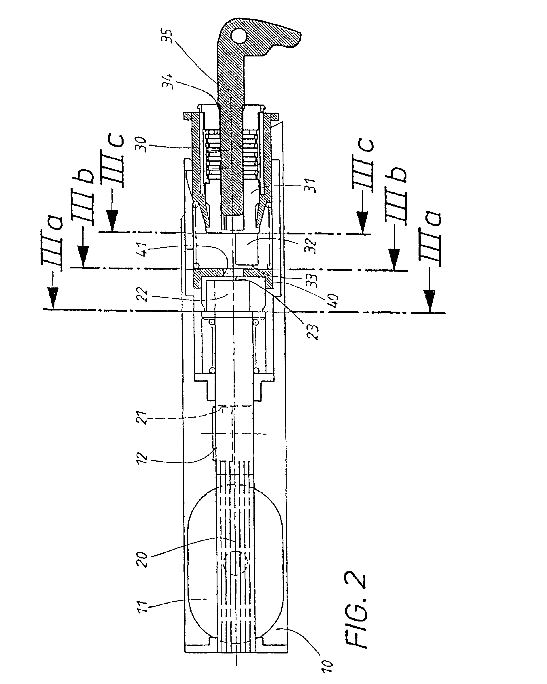
[0007]In accordance with the invention, the transmission element is a shaft, which is supported with freedom of both axial movement and rotation. The rotation of this shaft is accomplished by a first securing device, preferably a central locking unit. The actuating element has an area which can be rotated independently of the shaft and its securing device by means of a second securing device, preferably a cylinder lock. Each of these two elements has at least one eccentric extension, and the end surfaces of these extensions are arranged to face each other. The actuation of one of the securing devices provided has the effect of changing the relative rotational position of the two opposing, facing extensions. It is provided in accordance with the invention that the end surfaces of the extensions overlap in certain relative rotational positions, whereas, in other rotational positions, they do not overlap. When the actuating element is actuated while it is in an overlapping position, the extension of the rotating area of the actuating element comes up against the end surface of the shaft extension. As a result, the movement of the actuating element can be converted into the linear movement of the axially movable shaft. When the actuating element is actuated while in a nonoverlapping position, however, it extension does not come up against a stop, for which reason no axial movement of the shaft which could release the lock mechanism takes place. The overall device therefore serves a securing function in all of the nonoverlapping positions. Increasing the amount of force being applied to the actuating element cannot lead to the destruction of this element and forcibly activate the lock mechanism.
[0008]The independent rotational ability of the shaft and of the rotating area of the actuating element makes it possible for one of the extensions, preferably that of the actuating element, to be moved to an absolute rotational position in which no overlapping with the other extension is possible, no matter which of its predetermined absolute positions the other extension may be occupying. In this position, which is referred to below as the “hotel position”, the vehicle can be moved by any
third party in possession of a release device for the central locking
system, whereas personal objects stowed in a compartment equipped with the actuating device according to the invention are securely protected. When the extension of the actuating element is in another rotational position, which can be selected by the authorized user and which is referred to below as the “
normal position”, however, the overlap depends on the absolute position of the shaft extension, so that the storage compartment equipped with the actuating device according to the invention can be secured or released jointly by the central locking unit.
[0009]To accomplish this task, it is proposed according to the invention in correspondence with the characterizing clause of claim 2 that a nonrotatable locking disk be installed axially between the extensions, this disk being provided with an opening, the shape of which allows the extension of the actuating element to pass through only when this extension is in certain absolute rotational positions, whereas the extension is mechanically prevented from passing through in all other rotational positions. This design offers the following advantages:
[0010]If the extension of the actuating element is in an “allowed” position and the actuating element is actuated, the extension will be able to pass through the opening in the locking disk and strike the extension of the axially movable shaft if the shaft is in the proper absolute rotational position, as a result of which the lock mechanism can be released. If, while this working connection is established, the rotating area of the actuating element were to be turned by mistake, the end surfaces of the extensions could slide off each other, which would lead to a malfunction. The positive engagement of the extension of the actuating element in the opening of the nonrotating locking disk, however, effectively prevents the actuating element from rotating. A malfunction is thus excluded. In addition, the provision of the locking disk has the result that the extension itself can pass through only in the “allowed” position or positions, that is, only after it has traveled an absolute rotational distance. This gives the user an enhanced impression of a precision mechanism.

