
Valve assembly

Inactive Publication Date: 2005-05-03
MAQUET CRITICAL CARE
View PDF12 Cites 36 Cited by
  • Summary
  • Abstract
  • Description
  • Claims
  • Application Information

AI Technical Summary

Benefits of technology

[0007]An object of the present invention is to provide a valve assembly that at least minimizes the problems associated with known valve assemblies, as discussed above.
[0009]By replacing the mechanical bearing which guides the movable shaft with a magnetic bearing, either active or passive or a combination of the two, the frictional force between the movable shaft and the bearing is effectively eliminated. The need for sophisticated means for controlling friction between the shaft and the bearing is thus obviated.
[0010]Additionally, the magnetic bearing may be configured to act on the movable shaft to produce a magnetic biasing toward either closing or opening the valve, as desired, in the absence of a force applied to the shaft by the force generator. This has the advantage that magnetic bearing can replace or augment biasing means typically employed in a valve assembly to be used in safety critical applications, such as an inspiration or an expiration flow control valve in a pneumatic circuit of a conventional mechanical ventilator, where for patient safety reasons it is preferable that, respectively, the valve closes or opens in the event of a failure of the force generator.

Problems solved by technology

In a valve assembly having a mechanically journaled shaft friction in the bearing can cause problems.
One of the most common is that frictional forces often cause the shaft to stick in a particular position so that a change in the force applied to the shaft in order to move it to another position can have unpredictable results.
Moreover, the magnitude of the frictional force itself is often unpredictable, since it may change with the age of the valve, the pressure of the shaft against the bearing or with movement of the shaft within the bearing in a direction not associated with the sealing or un-sealing of the valve opening, so that the force from the force generator which must be applied to the shaft in order to overcome the frictional force can be unpredictable.

Method used


Image

  • Valve assembly
  • Valve assembly
  • Valve assembly

Examples


Embodiment Construction

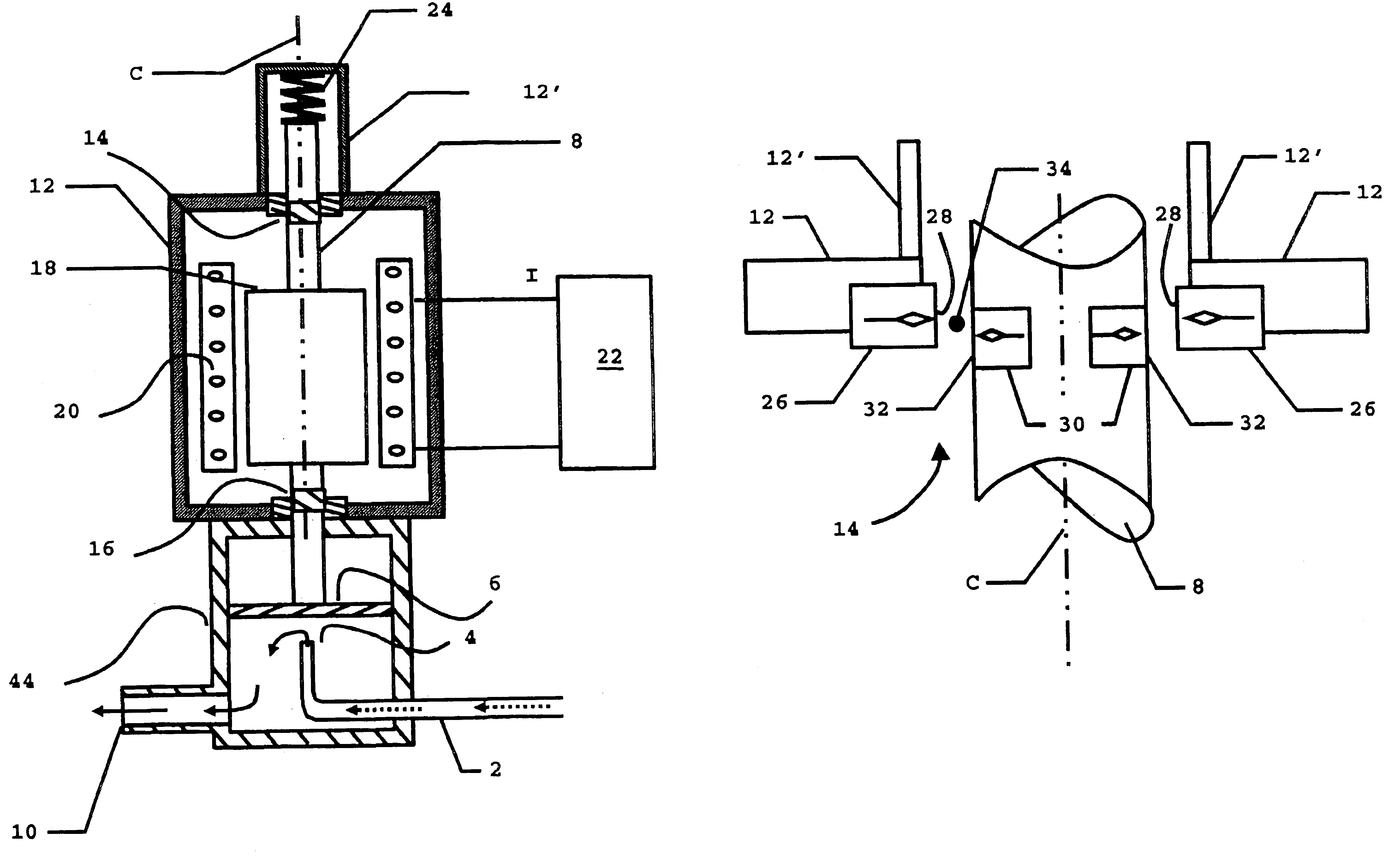
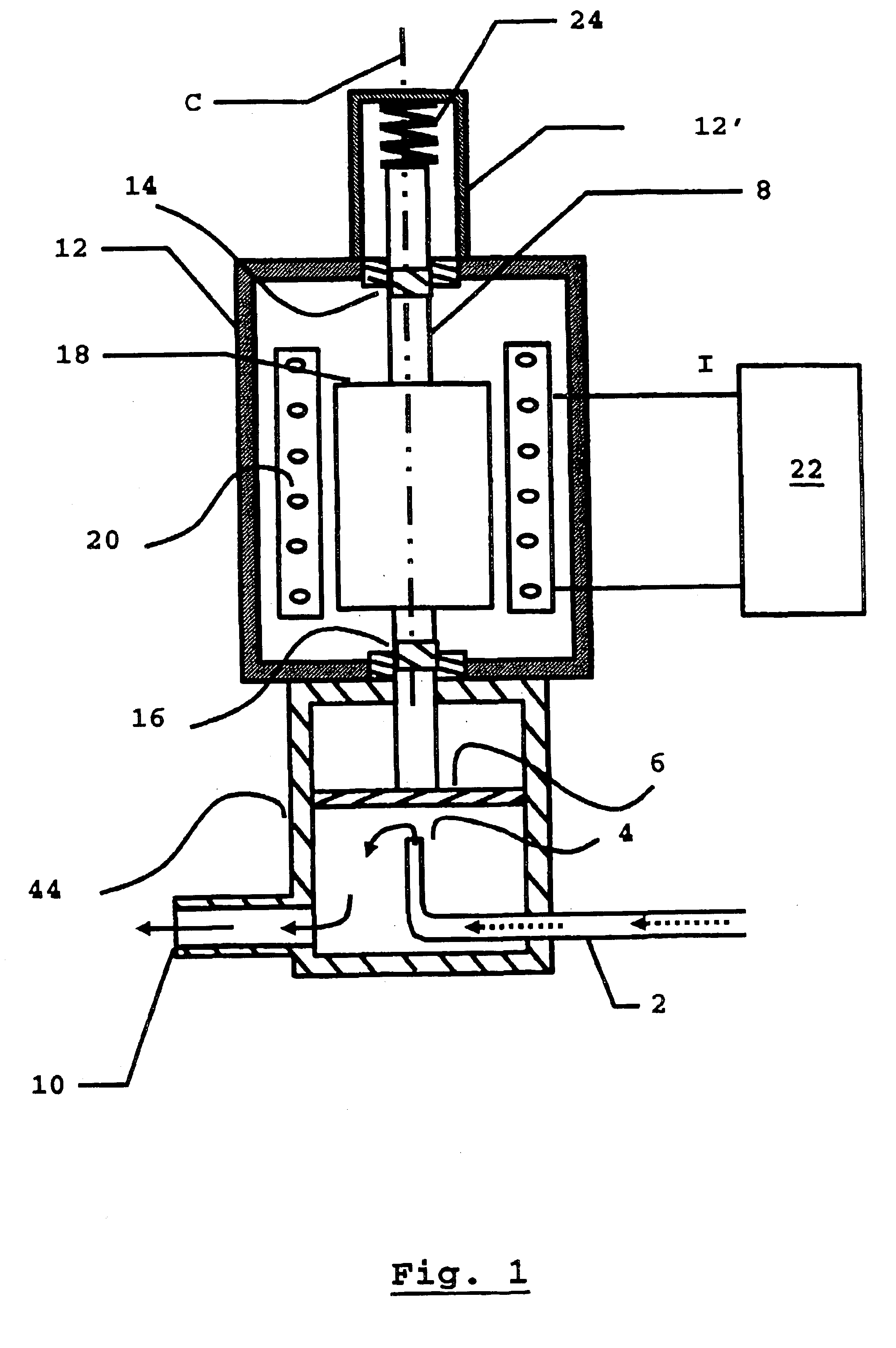
[0014]As shown in FIG. 1, an electromagnetic valve assembly has a valve 44 with an inlet 2, the opening 4 of which can be opened and closed with a membrane 6.

[0015]The membrane 6 is elastically resilient. To close the valve 44, a movable shaft 8 pushes the membrane 6 against the opening 4. To open the valve 44, the movable shaft 8 retracts, (upward in FIG. 1), whereupon the membrane 6 moves resiliently away from the opening 4, to allow a flow through the inlet 2, via the opening 4, and out through an outlet 10.

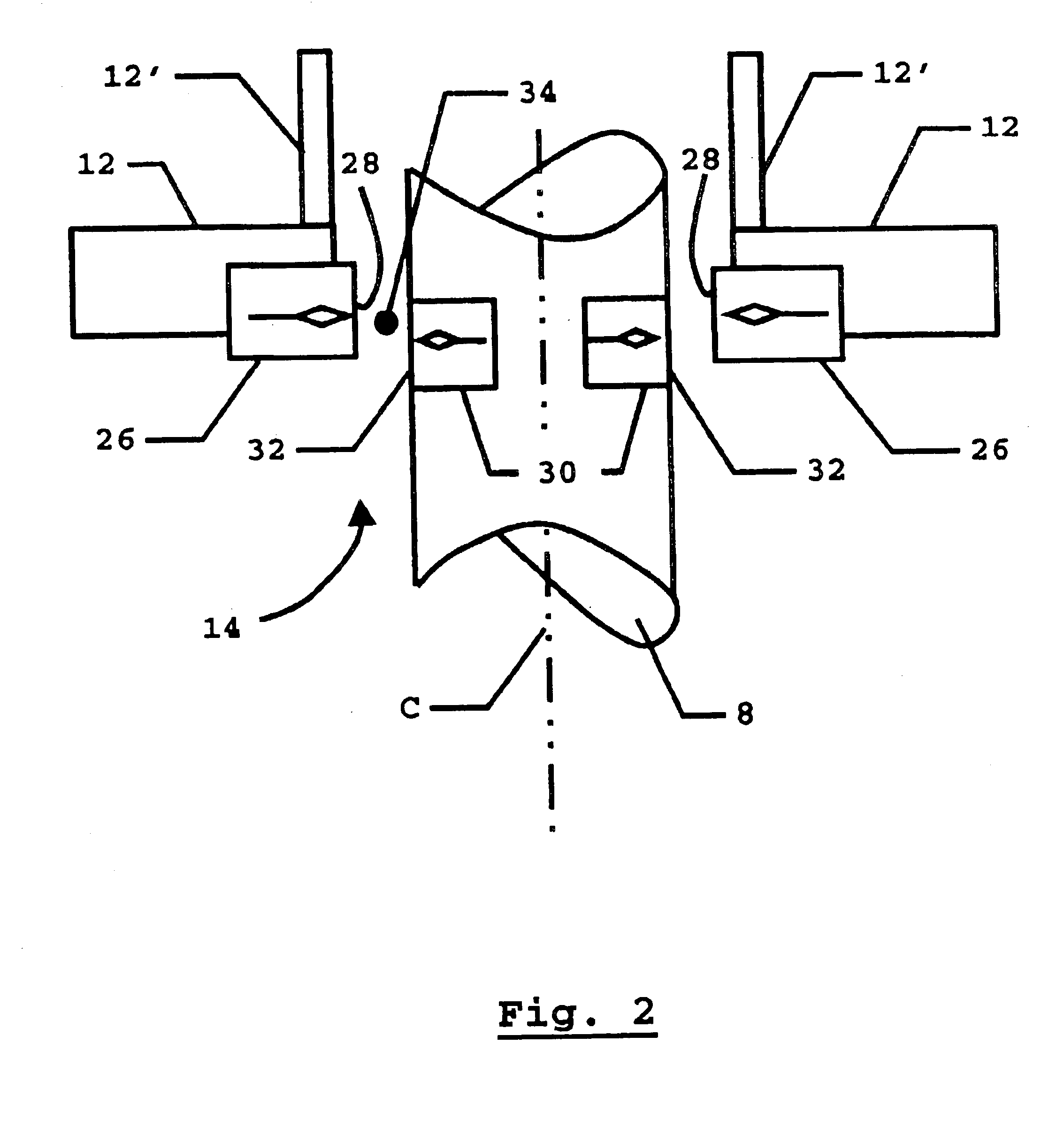
[0016]The movable shaft 8 passes through an enclosure 12 and is supported in magnetic bearing assemblies 14 and 16 for movement in its longitudinal direction along a movement axis that is, in the present example, the coil axis C (an axis of symmetry of a solenoid coil 20 along which it is wound). The bearing assemblies 14, 16 thus serve to guide the movable shaft 8.

[0017]An armature 18 made of magnetic material is fixed on the movable shaft 8 and is located inside the solenoid...


PUM


Abstract

A valve assembly has a valve opening which can be sealed and un-sealed by movement of a membrane 6, a force generator, such as an electromagnetic force generator having a solenoid and armature arrangement, and a shaft that is operably connected to the membrane and which is movable along a movement axis under the influence of the generated force to move the membrane and thereby regulate the degree of opening of the valve. Bearing assemblies are provided to procure a magnetic suspension of the shaft, permit its movement along the axis, and also to optionally produce a magnetic biasing of the shaft in a direction along the axis, particularly in the absence of a generated force.

Description

BACKGROUND OF THE INVENTION[0001]1. Field of the Invention[0002]The present invention relates to a valve assembly and in particular to an assembly of the type in which regulation of the flow of fluid through the valve is achieved by means of translational and / or rotational movement of a shaft to seal or un-seal a valve opening in response to an applied force from an associated force generator.[0003]2. Description of the Prior Art[0004]In a valve assembly having a mechanically journaled shaft friction in the bearing can cause problems. One of the most common is that frictional forces often cause the shaft to stick in a particular position so that a change in the force applied to the shaft in order to move it to another position can have unpredictable results. Moreover, the magnitude of the frictional force itself is often unpredictable, since it may change with the age of the valve, the pressure of the shaft against the bearing or with movement of the shaft within the bearing in a di...

Claims


Application Information

Patent Timeline
IPC IPC(8): F16K31/08F16C32/04F16K31/06
CPCF16K31/084F16K31/082
Inventor HALLBACK, MANGUSLARSSON, .ANG.KEJALDE, FREDRIK
Owner MAQUET CRITICAL CARE
Features
  • Generate Ideas
  • Intellectual Property
  • Life Sciences
  • Materials
  • Tech Scout
  • Unparalleled Data Quality
  • Higher Quality Content
  • 60% Fewer Hallucinations
Learn More