Breakaway support post for highway guardrail end treatments

a technology for guardrail end treatments and breakaway support posts, which is applied in roadway safety arrangements, roadways, construction, etc., can solve the problems of early guardrail end treatments that often had no protection at the end facing oncoming traffic, extensive damage to vehicles, and substantial danger to drivers and passengers of vehicles, so as to enhance the desired yielding characteristics, facilitate initial installation and repair, and minimize damage to an impacting vehicle

Inactive Publication Date: 2005-05-03
TRINITY IND INC
View PDF120 Cites 37 Cited by
  • Summary
  • Abstract
  • Description
  • Claims
  • Application Information

AI Technical Summary

Benefits of technology

[0011]In accordance with teachings of the present invention, various shortcomings of previous guardrail support posts associated with highway guardrail end treatments have been addressed. The present invention provides a breakaway support post which will buckle or yield during head-on impact by a vehicle at or near the extreme end of an associated guardrail to minimize damage to the vehicle and provide sufficient strength to direct a vehicle back onto an associated roadway during a rail face impact with the guardrail downstream from the guardrail end treatment. The use of breakaway support posts incorporating teachings of the present invention substantially reduces the time and cost associated with initial installation of a guardrail end treatment and repair of the guardrail end treatment following impact by a motor vehicle.
[0012]One aspect of the present invention includes providing a breakaway support post having one or more slots formed in the support post to allow the support post to buckle or yield in response to forces applied to the support post in a first direction by an impacting vehicle without causing excessive damage to the vehicle. The orientation and location of the slots are selected to allow the support post to effectively anchor the guardrail to direct an impacting vehicle back onto an adjacent roadway in response to forces applied to the support post in a second direction during a downstream rail face impact. For some applications, one or more plates may be attached to the breakaway support post and inserted into the soil to provide additional support during a rail face impact with the associated guardrail and to provide more reliable buckling or yielding of the breakaway support post during a head-on impact with one end of the associated guardrail. Alternatively, the length of the portion of the breakaway support post inserted into the soil may be increased to enhance these same characteristics. For some applications, the breakaway support post may have a typical I-beam cross section with slots formed in one or more flange portions of the I-beam. Alternatively, the breakaway support post may have a hollow, rectangular or square cross section with slots formed in one or more sides of the post in accordance with teachings of the present invention.
[0014]Technical advantages of the present invention include providing breakaway support posts which are easier to initially install and to repair as compared to wooden breakaway support posts. Major portions of each breakaway support post may be fabricated from standard, commercially available steel I-beams using conventional metal bending and stamping techniques in accordance with teachings of the present invention. One or more metal soil plates may be attached to each breakaway support post to further enhance desired characteristics of yielding or buckling during head-on impact with one end of an associated guardrail to minimize damage to an impacting vehicle and to securely anchor the associated guardrail to redirect an impacting vehicle back onto the adjacent roadway after a rail face impact. Breakaway support posts incorporating teachings of the present invention may be used with a wide variety of guardrail end treatments having various types of energy absorbing assemblies located at or near the end of the associated guardrail facing oncoming traffic. For many applications, breakaway support posts may be satisfactorily installed adjacent to the edge of a roadway without the use of steel foundation tubes and / or concrete foundations typically associated with installing wooden breakaway support posts and other types of breakaway support posts.
[0015]A further aspect of the present invention includes providing guardrail support posts having a first portion or upper section attached or coupled, at least in part, by a frangible connection, to a second portion or lower section. The support post and frangible connection may be oriented in accordance with teachings of the present invention to resist impact by a motor vehicle from one direction (strong direction), and to yield to impact by a motor vehicle from another direction (weak direction). Preferably, the fragile connection allows the upper portion of the post to deflect slightly and then break off of the lower portion, thus minimizing lifting of the impacting vehicle into the air.

Problems solved by technology

Along most highways there are hazards which present substantial danger to drivers and passengers of vehicles if the vehicles leave the highway.
Early guardrail systems often had no protection at the end facing oncoming traffic.
Sometimes impacting vehicles became impaled on the end of the guardrail causing extensive damage to the vehicle and severe injury to the driver and / or passengers.
In some reported cases, the guardrail penetrated directly into the passenger's compartment of the vehicle fatally injuring the driver and passengers.
A head-on collision with a guardrail support post located at the end of a guardrail system may result in vaulting the impacting vehicle.
Also, improper installation of the top plate relative to the bottom plate, such as over tightening of the associated mechanical fasteners, may prevent proper functioning of the slip base.
However, impact of a vehicle with a wooden breakaway support post may often result in substantial damage to the adjacent soil.
Removing portions of a broken wooden post from the soil is often both time consuming and further damages the soil.
Such metal sleeves and / or concrete foundations are relatively expensive and time consuming to install.

Method used


Image

  • Breakaway support post for highway guardrail end treatments
  • Breakaway support post for highway guardrail end treatments
  • Breakaway support post for highway guardrail end treatments

Examples


Embodiment Construction

[0036]The preferred embodiments of the present invention and its advantages are best understood by referring to the FIGS. 1 through 16 of the drawings, like numerals being used for like and corresponding parts of the various drawings.

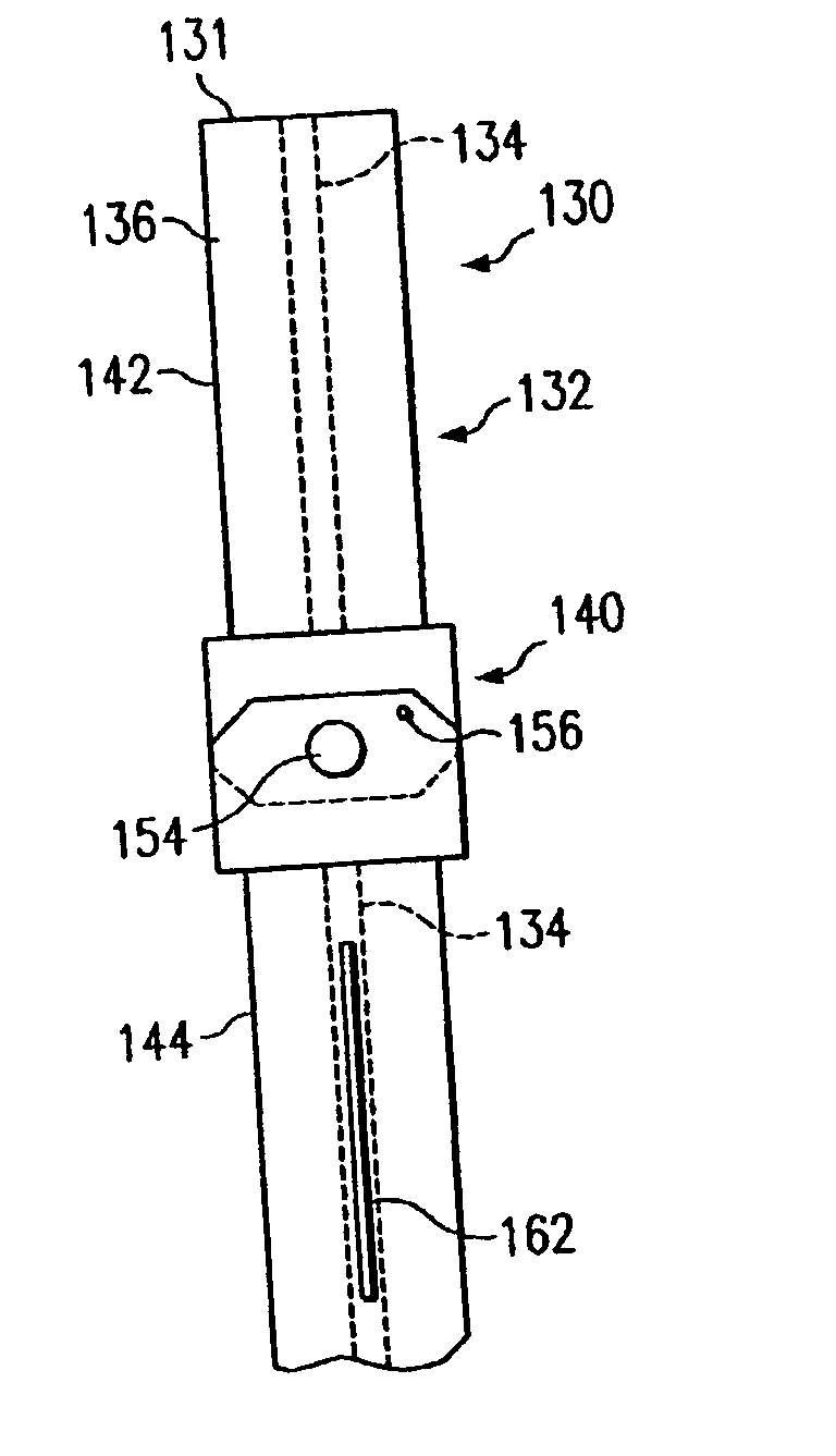
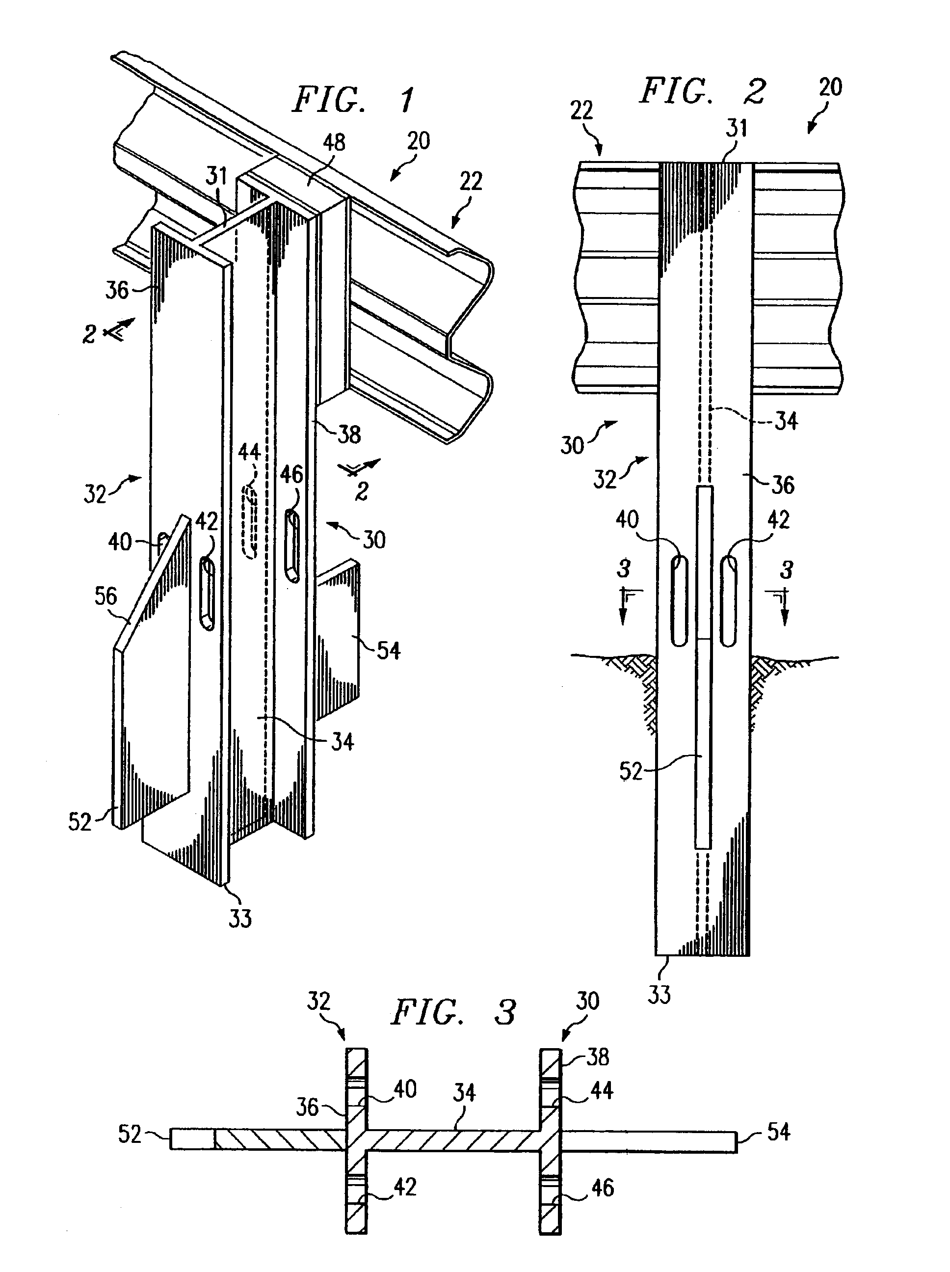
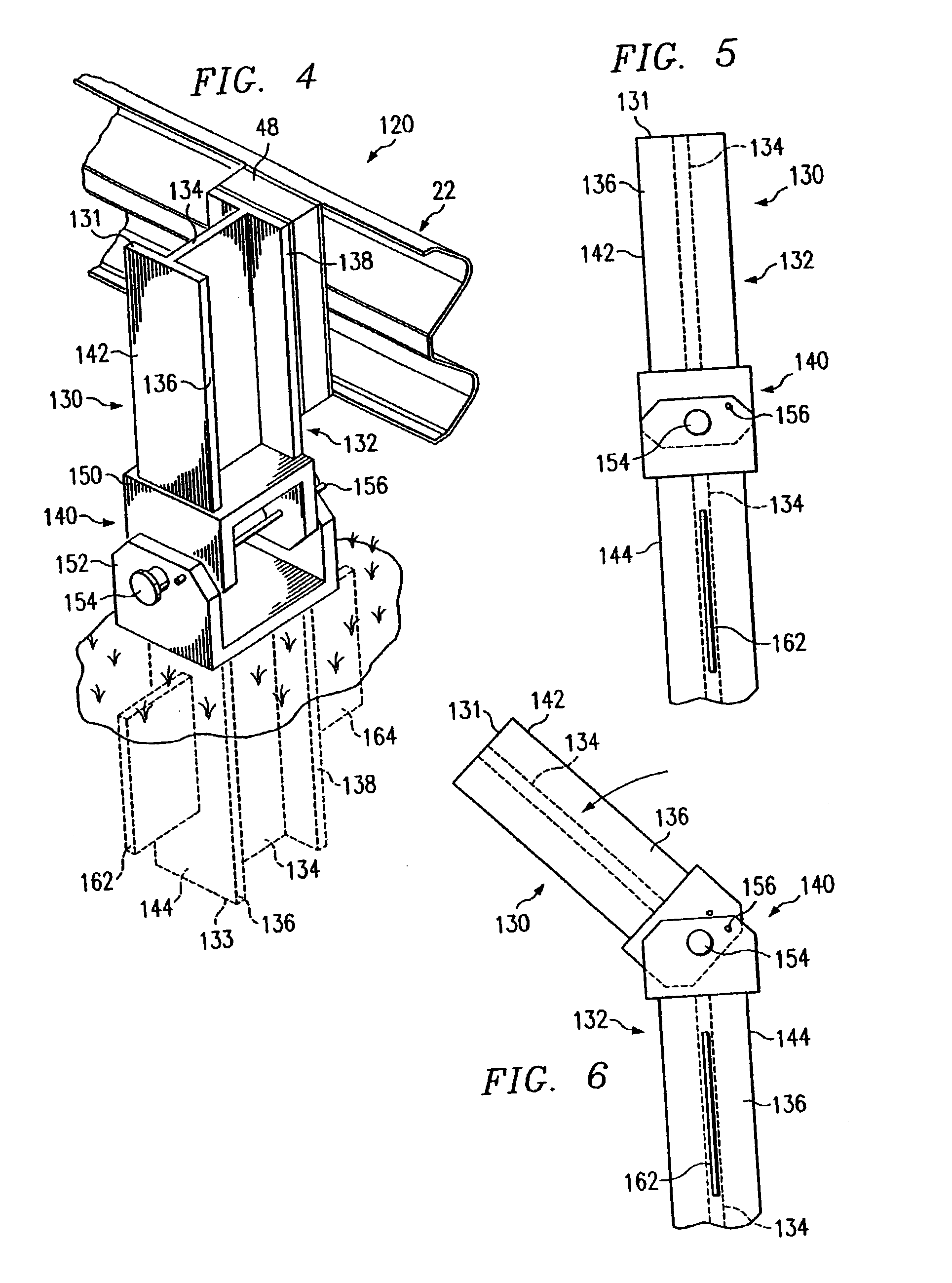
[0037]Portions of highway guardrail system 20 incorporating one embodiment of the present invention are shown in FIGS. 1, 2 and 3. Portions of highway guardrail systems 120, 220, and 320 incorporating alternative embodiments of the present invention are shown in FIGS. 4 through 13. Breakaway support posts incorporating further embodiments of the present invention are shown in FIGS. 14A through 16. Highway guardrail systems 20, 120, 220, and 320 are typically installed along the edge of a highway or roadway (not expressly shown) adjacent to a hazard (not expressly shown) to prevent a vehicle (not shown) from leaving the associated highway or roadway.

[0038]Guardrail systems 20, 120, 220, and 320 are primarily designed and installed along a highway to with...


PUM


Abstract

A support post for a guardrail which resists impact by a motor vehicle from one direction (strong direction) and yields to impact by a motor vehicle from another direction (weak direction). The support post is adapted to receive the guardrail such that the rail face of the guardrail runs generally perpendicular to the strong direction such that the support post resists an impact on the rail face of the guardrail and yields to an impact force on the end of the guardrail.

Description

CROSS REFERENCE TO RELATED APPLICATIONS[0001]This application is a continuation from U.S. patent application Ser. No. 09 / 074,496, filed on May 7, 1998 by James R. Albritton and entitled “Breakaway Support Post for Highway Guardrail End Treatments” that claims benefit of U.S. Provisional Application Ser. No. 60 / 046,015 filed May 9, 1997.[0002]The application is also related to U.S. Divisional patent application Ser. No. 09 / 835,282 filed Apr. 12, 2001 and entitled “Breakaway Support Post for Highway Guardrail End Treatments”, now U.S. Pat. No. 6,488,268 B1, and U.S. Divisional application Ser. No. 10 / 210,444 filed Aug. 1, 2002 and entitled “Breakaway Support Post For Highway Guardrail End Treatments”, now U.S. Pat. No. 6,793,204.TECHNICAL FIELD OF THE INVENTION[0003]The present invention relates to highway guardrail systems having a guardrail mounted on posts, and more particularly, to guardrail end treatments designed to meet applicable federal and state safety standards including bu...

Claims


Application Information

Patent Timeline
Patent Type & Authority Patents(United States)
IPC IPC(8): E01F9/018E01F15/02E01F9/011E01F15/04
CPCE01F9/0182E01F15/0461Y10T403/11E01F9/635F16B2200/63
Inventor ALBRITTON, JAMES R.
Owner TRINITY IND INC
Why Eureka
Try Eureka