

Electromechanical locking mechanism
- Summary
- Abstract
- Description
- Claims
- Application Information
AI Technical Summary
Benefits of technology
Problems solved by technology
Method used
Image

Examples
Embodiment Construction
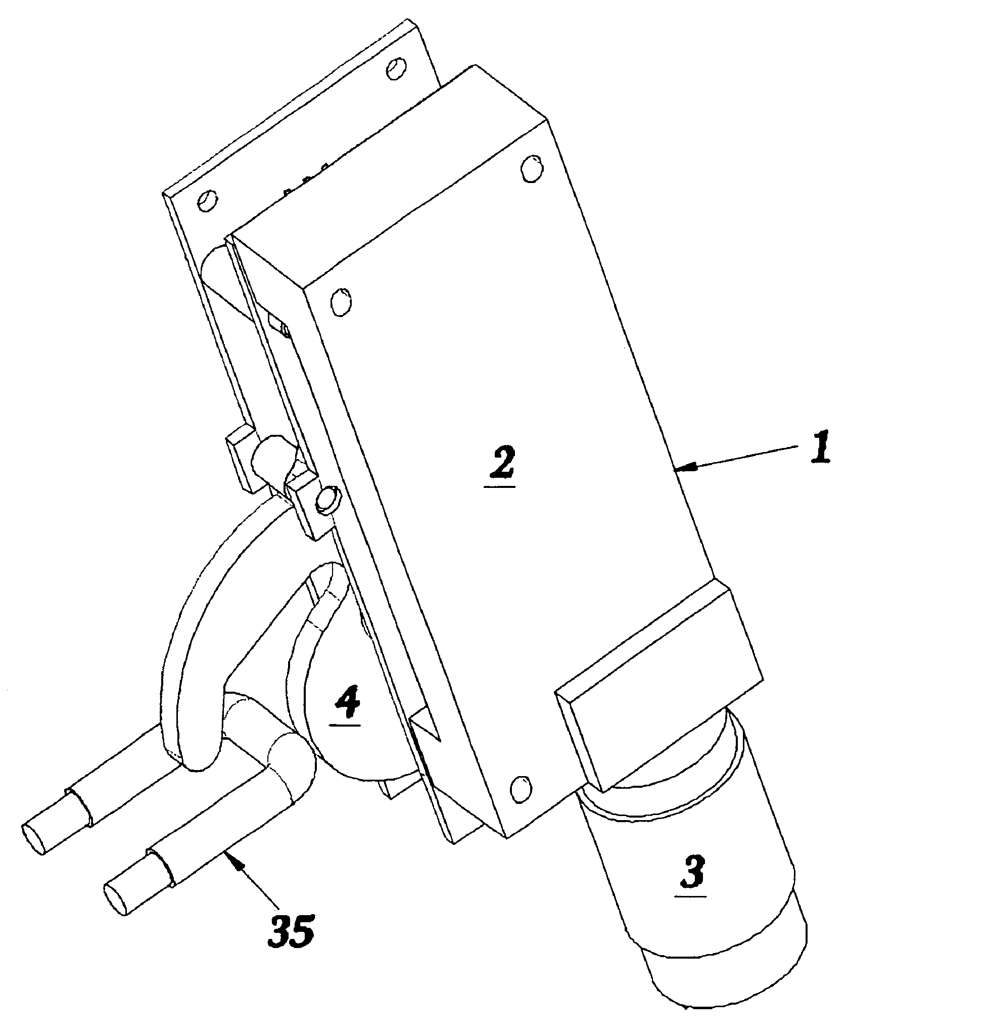
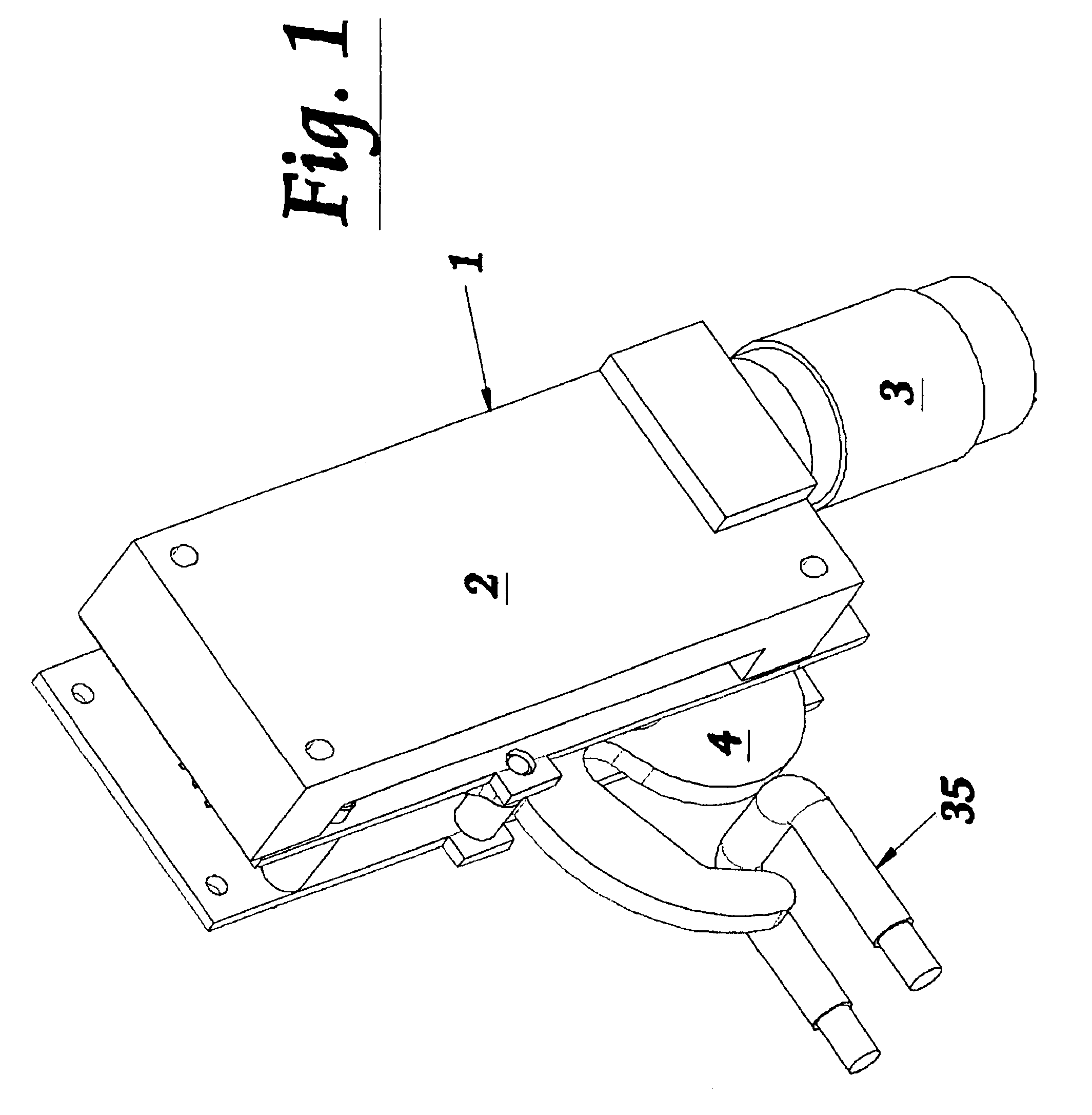
[0022]Turning first to FIG. 1, reference numeral 1 designates the gear motor, which includes a motor 3 and a gear box 2. The gear motor is coupled, through a linkage mechanism, to drive locking hook 4, which engages and pulls in u-bolt 35.
[0023]This u-bolt 35 could be substituted for a headed bolt and the locking hook 4 could be substituted for a claw shaped device which would grab the headed bolt around the head and pull it in.
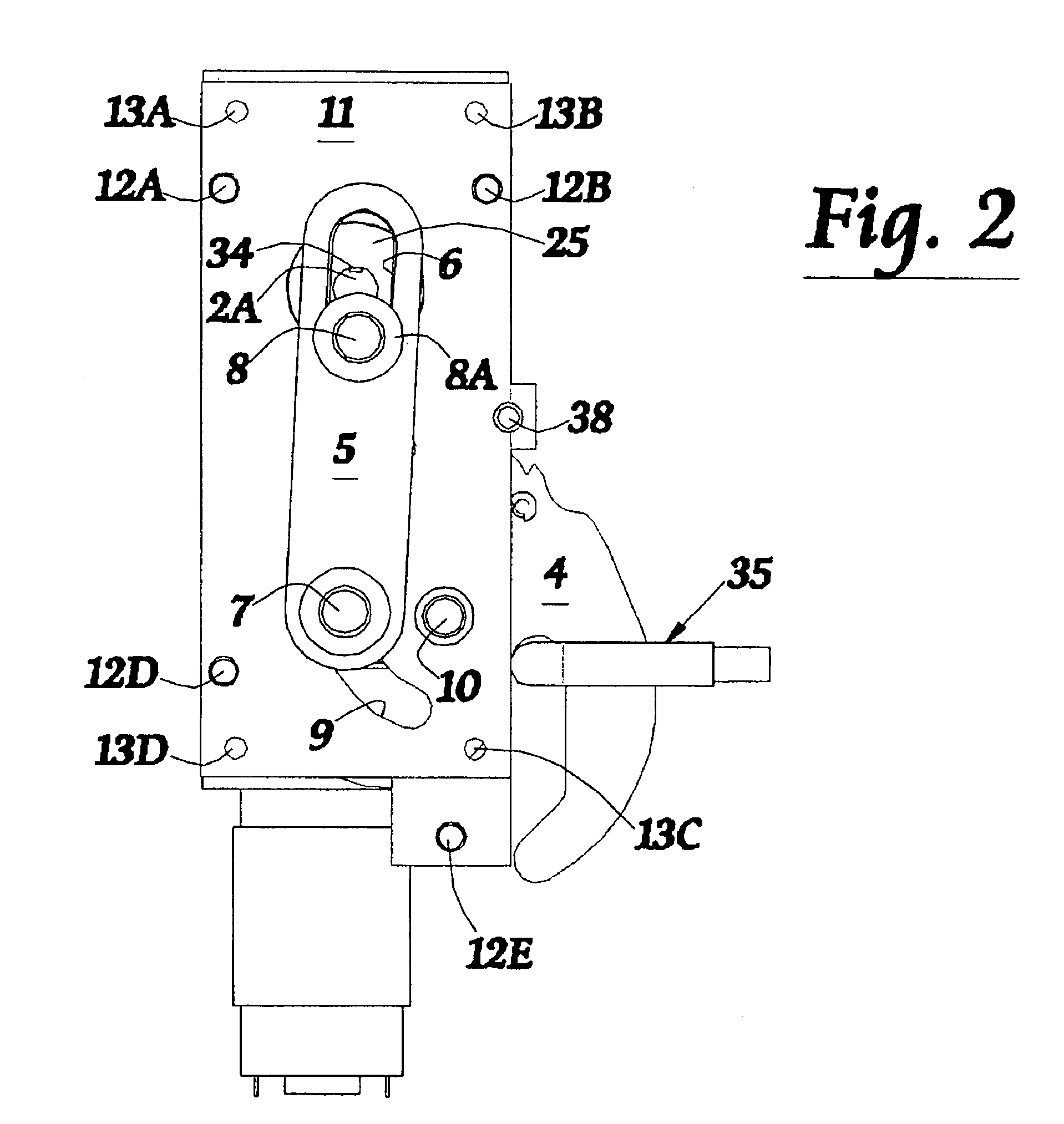
[0024]Turning now to FIG. 2, the left side view of the lock is illustrated. The output shaft 2a of the gearbox 1 is coupled to multifunction wheel 25 with key 34. The multifunction wheel 25 rotates, moving motor pull point 8 in a counterclockwise fashion (in this view). As the motor pull point moves, it pulls link 5 by cam follower 8A sliding up slot 6 which is integral to link 5. When the end of slot 6 is reached, link 5 begins to move in an upwardly fashion, rotating locking hook 4 about locking hook fulcrum 10. The locking hook 4 is pulled at locking hook ...
PUM
 Abstract
Description
Claims
Application Information