Power tools having wire guides for lights

a technology of power tools and wire guides, which is applied in the direction of portable power-driven tools, coupling device connections, lighting and heating apparatus, etc., can solve the problems of affecting the operation of machining, affecting the appearance of routers, etc., and achieves the effect of facilitating the wiring of lighting circuits and not affecting machining operations

Inactive Publication Date: 2005-05-03
MAKITA CORP
View PDF15 Cites 23 Cited by
  • Summary
  • Abstract
  • Description
  • Claims
  • Application Information

AI Technical Summary

Benefits of technology

[0008]It is, accordingly, one object of the present teachings to provide improved lighted power tools. For example, in one aspect of the present teachings, lighted power tools may include one or more wire guides that facilitate the wiring of a lighting circuit to a power source and do not hinder machining operations.

Problems solved by technology

However, by disposing the electric line in this manner, the appearance of the router may be degraded and a possibility exists that the electric line will hinder the machining operation.

Method used


Image

  • Power tools having wire guides for lights
  • Power tools having wire guides for lights
  • Power tools having wire guides for lights

Examples


Embodiment Construction

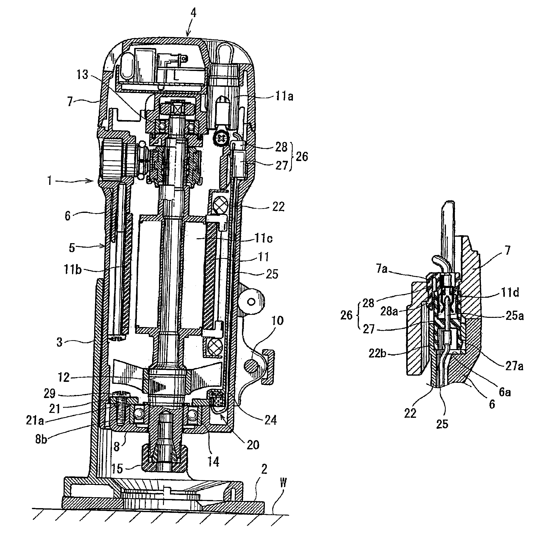
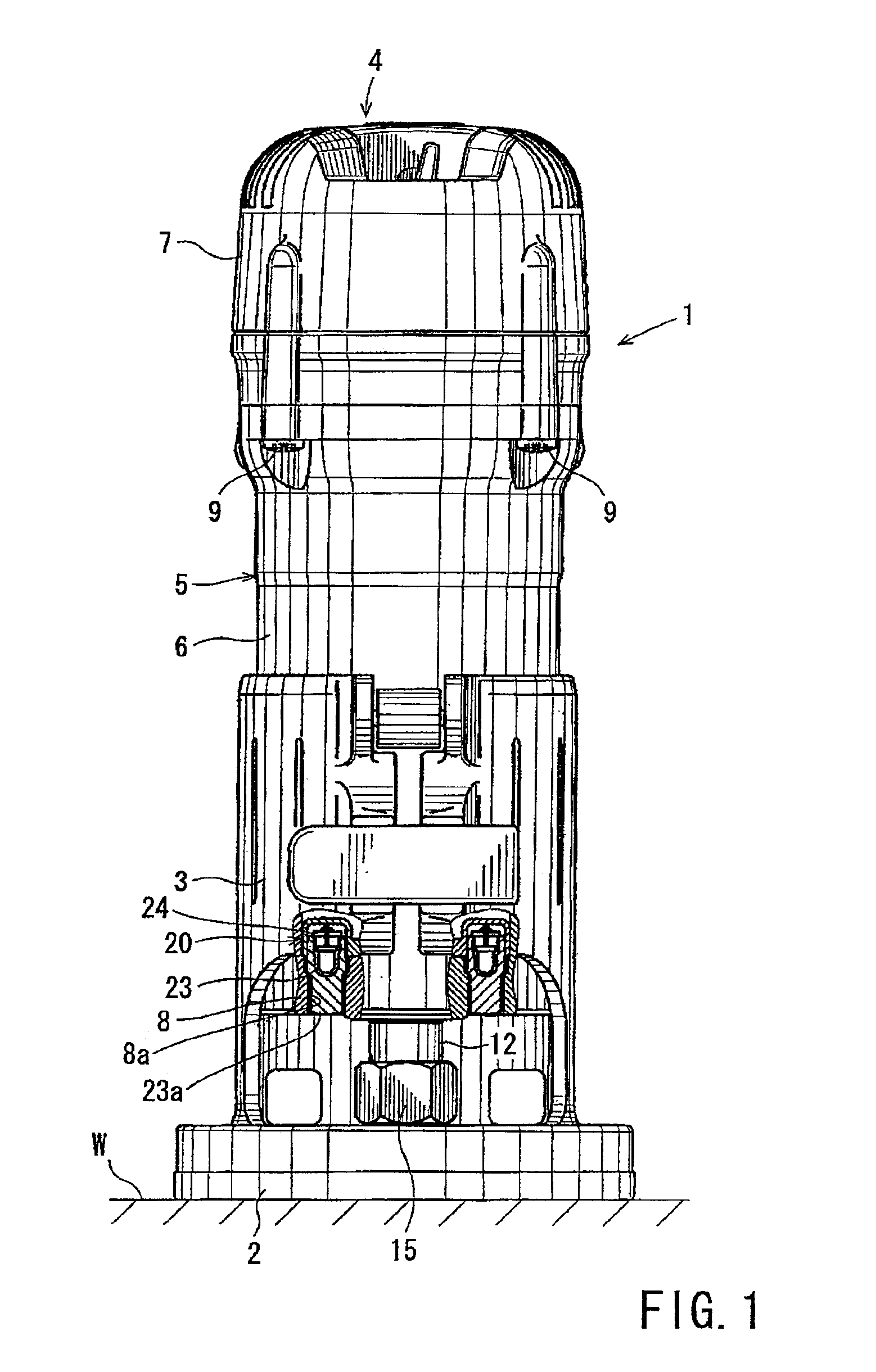
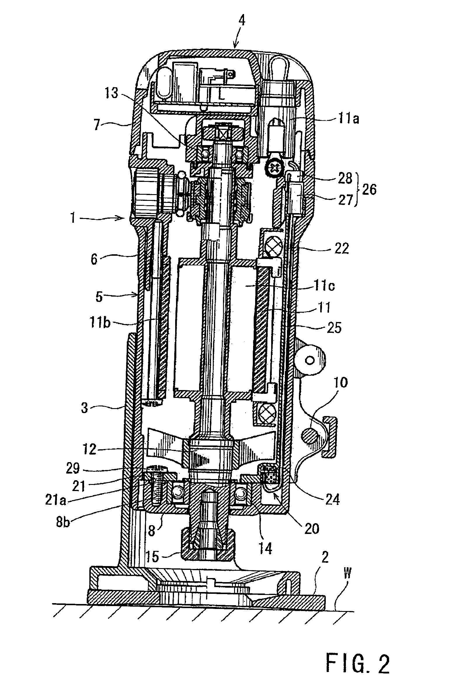
[0024]In one embodiment of the present teachings, power tools may include a housing that has a housing wall. An electric motor may be disposed on or within the housing. A lighting device may be mounted on or within the housing and may include an electric light that is connected to a power source via an electric line. A wire guide preferably retains or supports at least a portion of the electric line. The wire guide may be mounted so as to extend along the housing wall. In this case, the wiring operation can be easily performed and the electric line may be reliably held or retained by the wire guide. The wire guide also may prevent the electric line from being exposed to the environment outside of the housing. Therefore, the electric line preferably does not interfere with machining operations.

[0025]In another embodiment of the present teachings, the lighting device may include a light base and the electric light. The wire guide may be mounted on or formed integrally with the light b...


PUM

PropertyMeasurementUnit
currentaaaaaaaaaa
areaaaaaaaaaaa
electricaaaaaaaaaa

Abstract

Power tools (1) may include an electric motor (11) disposed within a housing (5). A lighting device (20) may be mounted on the housing and may serve to illuminate the area around a tool bit and/or a portion of a workpiece (W) that will be machined by the tool bit. An electric light (23) may be connected to a power source circuit (11a) via an electric line that includes electric wires (25). In order to facilitate the wiring operation, a wire guide (22, 122) preferably supports or retains at least a portion of the electric line. The wire guide may be mounted on the housing such that the wire guide extends along an inner surface or an outer surface of the housing. In the alternative, the electric line may be disposed within a recess (31) defined within an inner surface or an outer surface of the housing. In either case, the electrical line can be easily wired or installed and the electric line preferably does not interfere with machining operations during operation of the power tool.

Description

[0001]This application claims priority to Japanese application serial number 2001-145026, which application is hereby incorporated by reference herein in its entirety.BACKGROUND OF THE INVENTION[0002]1. Field of the Invention[0003]The present invention relates to power tools, such as power routers and power screwdrivers. More specifically, the present invention relates to power tools that include one or more lights for illuminating an area around a tool bit and / or a portion of a workpiece that will be machined by the power tool, and one or more wire guides for retainably supporting an electric line connecting the light(s) to a power source.[0004]2. Description of the Related Art[0005]U.S. Pat. No. 4,051,880 teaches a power router that includes a light for illuminating the area proximal to a tool bit. More specifically, the light serves to illuminate the area around a chuck that holds the tool bit, i.e., the portion of a workpiece that will be machined by the router. The light is int...

Claims


Application Information

Patent Timeline
Patent Type & Authority Patents(United States)
IPC IPC(8): B25F5/00B25F5/02B27C5/00B27C5/10B25B23/18
CPCB25F5/021B27C5/10Y10T409/306608
Inventor HARA, AKIHITOUTSUNO, ATSUSHI
Owner MAKITA CORP
Why Eureka
Try Eureka