Turbine and manufacturing method therefor

a technology of turbines and manufacturing methods, applied in the field of turbines, can solve the problems of relatively fragile particles, and achieve the effect of easy restoration and remaking

Inactive Publication Date: 2005-05-03
MITSUBISHI HEAVY IND LTD
View PDF18 Cites 18 Cited by
  • Summary
  • Abstract
  • Description
  • Claims
  • Application Information

AI Technical Summary

Benefits of technology

[0009]The present invention was made in consideration of the above-explained problems. An object of the present invention is to provide a turbine in which appropriate clearance can be always maintained between the rotor blade unit and the shroud and which can operate for longer periods under high-temperature conditions. Also, another object of the present invention is to provide a manufacturing method for a turbine which does not require a huge apparatus to manufacture, restore, and remake it.

Problems solved by technology

Although the reason was not clear, it is believed that these particles are relatively fragile.

Method used


Image

  • Turbine and manufacturing method therefor
  • Turbine and manufacturing method therefor
  • Turbine and manufacturing method therefor

Examples


Embodiment Construction

[0036]The invention disclosed herein may be variously modified and be in alternative forms. Specific embodiments therefor have been shown by way of example in the drawings and detailed description. It should be understood, however, that the drawings and detailed description thereof are not intended to limit the invention to the particular form disclosed, but on the contrary, the invention is to cover all modifications, equivalents and alternatives falling within the scope of the present invention as defined by the claims.

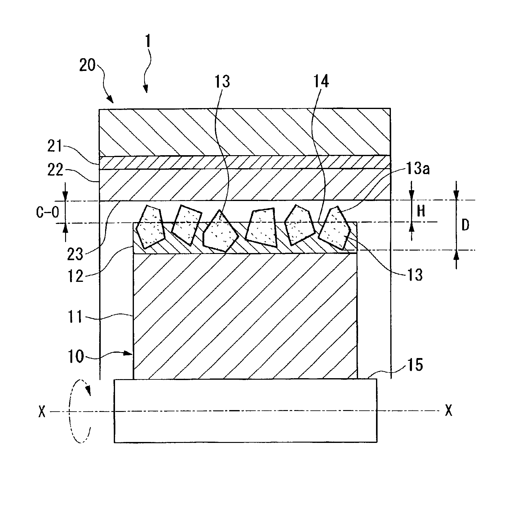
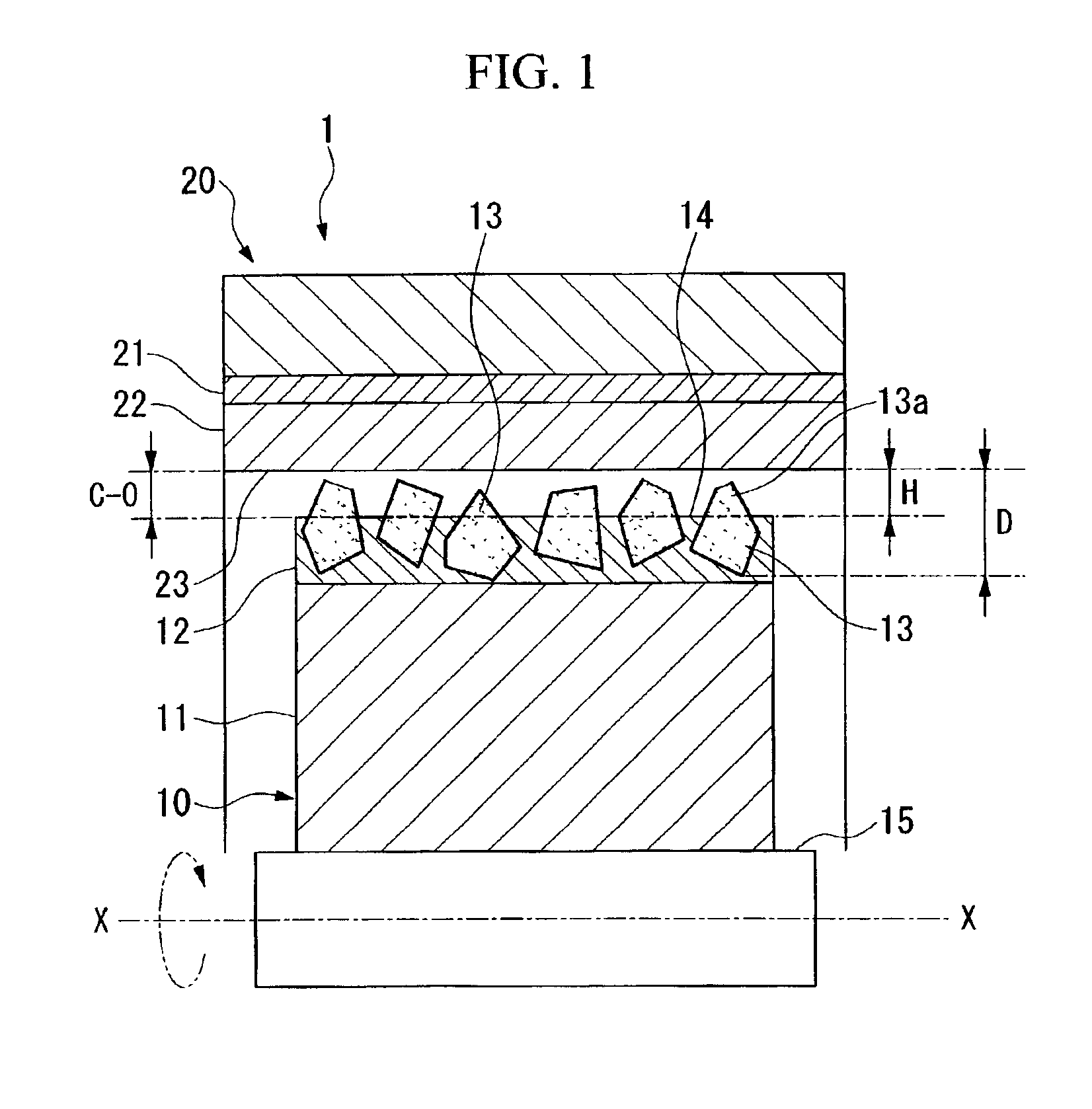
[0037]FIG. 1 is a cross section of a turbine according to an embodiment of the present invention. In FIG. 1, a turbine 1 comprises a rotor 10 and a shroud 20.

[0038]The rotor 10 comprises a shaft 15 which extends along a rotational axis X—X, a rotor blade unit 11 which extends from the shaft 15 radially, and an abradable layer 12 which is formed on the tip of the rotor blade unit 11. Numerous abrasive particles 13 are fixed on the abradable layer 12. Parts of abrasiv...


PUM

PropertyMeasurementUnit
diameteraaaaaaaaaa
temperatureaaaaaaaaaa
diameteraaaaaaaaaa

Abstract

A tip of rotor blade which rotates is an abradable surface. An inner wall of a shroud as a jacket for the rotor blade is an abrasive surface. A part of an abrasive particle protrudes from the abradable surface. When the tip of the rotor blade which rotates contacts the inner wall of the shroud, the protruding section of the abrasive particle slides with the abrasive surface so as to be ground. By doing this, a turbine which can maintain an appropriate clearance between the rotor blade and the shroud and can be used for a long period under high-temperature conditions with easy restoration and remaking thereof.

Description

BACKGROUND OF THE INVENTION[0001]1. Field of the Invention[0002]The present invention relates to a turbine which can maintain an appropriate clearance between an rotor blade and a shroud during an operation thereof.[0003]2. Description of Related Art[0004]In FIG. 4, an example of a turbine which is used for a gas turbine or a jet engine is known. A turbine 100 comprises a rotor 110 having a plurality of rotor blade unit 111 which are disposed along a rotating shaft X—X intermittently and a cone-shaped shroud 120 as a jacket for the rotor blade unit 111. Reference numeral 121 indicates a stator blade which extends from an inner wall of the shroud 120 so as to be disposed between the rotor blade unit 111. A high-pressure-fluid is introduced in to a turbine 100 from a smaller diameter region of the shroud 120, the rotor 110 rotates due to a force which is generated at screw surfaces of the rotor blade unit 111; thus, it is possible to convert kinetic energy of the fluid into a rotation...

Claims


Application Information

Patent Timeline
Patent Type & Authority Patents(United States)
IPC IPC(8): F01D11/08F01D5/14F01D5/20F01D11/12F01D5/28
CPCF01D11/12F01D11/122F05D2300/21F05D2230/237Y02T50/67Y02T50/60
Inventor OHARA, MINORUKUNITAKE, NOBUHIRO
Owner MITSUBISHI HEAVY IND LTD
Why Eureka
Try Eureka