Catalytically operating burner

a burner and catalytic technology, applied in the direction of catalytic material combustion, furnaces, combustion types, etc., can solve the problems of relative high ignition temperature of the gaseous reaction mixture, risk of overheating of the catalytic converter structure, etc., to improve the homogenous gas phase reaction, reduce the design length, and reduce the effect of ignition temperatur

Inactive Publication Date: 2005-05-03
ALSTOM TECH LTD
View PDF70 Cites 8 Cited by
  • Summary
  • Abstract
  • Description
  • Claims
  • Application Information

AI Technical Summary

Benefits of technology

[0028]According to a preferred variation of the burner according to the invention, one zone of the catalyzer structure that contains the inlet end can be equipped with turbulators and constructed catalytically inactive or inert, whereby in an area between the inlet end and outlet end of the catalyzer structure at least one catalytically active zone is constructed, and whereby one zone of the catalyzer structure containing the outlet end is equipped with turbulators and is constructed catalytically inactive or inert. This combination of characteristics creates a homogeneous reaction mixture in the inlet zone, whereby the inlet zone here also functions as a static mixer. Downstream from this inlet zone, the catalytic reaction then takes place in order to start the combustion of the mixture in a targeted manner. An intense mixing of the already burning or reacting partial streams of the individual channels then again takes place in order to prepare the homogeneous gas phase reaction in the final combustion chamber. This makes it particularly clear that the catalyzer structure does not only have the actual catalyzer function but, in addition, has the function of a static mixer at the inlet and the function of a mixer or turbulator at the outlet in order to improve the homogeneous gas phase reaction in the final combustion chamber, so that the latter's design length can be reduced.
[0029]In another alternative embodiment of the burner according to the invention, a zone of the catalyzer structure containing the inlet end can be equipped with turbulators and constructed catalytically highly active, whereby in an area between the inlet end and outlet end of the catalyzer structure a zone constructed without turbulators is constructed catalytically active, whereby a zone of the catalyzer structure containing the outlet end is equipped with turbulators. In this embodiment, the combustion reaction of the entering reaction mixture is already started at the inlet, whereby the highly active catalyst enables low ignition temperatures. Since no turbulators are arranged in the area following downstream, a relatively low pressure loss results so that relatively high flow speeds are present. This measure reduces the risk that the homogeneous gas phase reaction still ignites inside the catalyzer structure. An intensive mixing of the exiting individual streams is again achieved here in the outlet zone in order to improve the creation of the homogenous gas phase reaction.

Problems solved by technology

The main problems with this type of catalytic combustion are, on the one hand, the relatively high ignition temperature of the gaseous reaction mixture, for example, a fuel / air mixture.
On the other hand, there is the risk of an overheating of the catalyzer structure, particularly if a homogeneous gas phase reaction forms still within the catalyzer structure.
Another problem in the operation of a catalytically operating burner is that within a so-called “final combustion zone” downstream from the catalyzer structure only inadequate turbulence is present in the reaction mixture stream; this means that adequate combustion and minimal CO emissions within an appropriate dwell time in this final combustion zone can be realized only if this final combustion zone is relative large or long.
Other problems may occur because the catalytic reactions or conversions take place differently in the different channels of the catalyzer structure so that no homogeneous reaction state is present along the flow cross-section in the out-flowing mixture at the outlet of the catalyzer structure.

Method used


Image

  • Catalytically operating burner
  • Catalytically operating burner
  • Catalytically operating burner

Examples


second embodiment

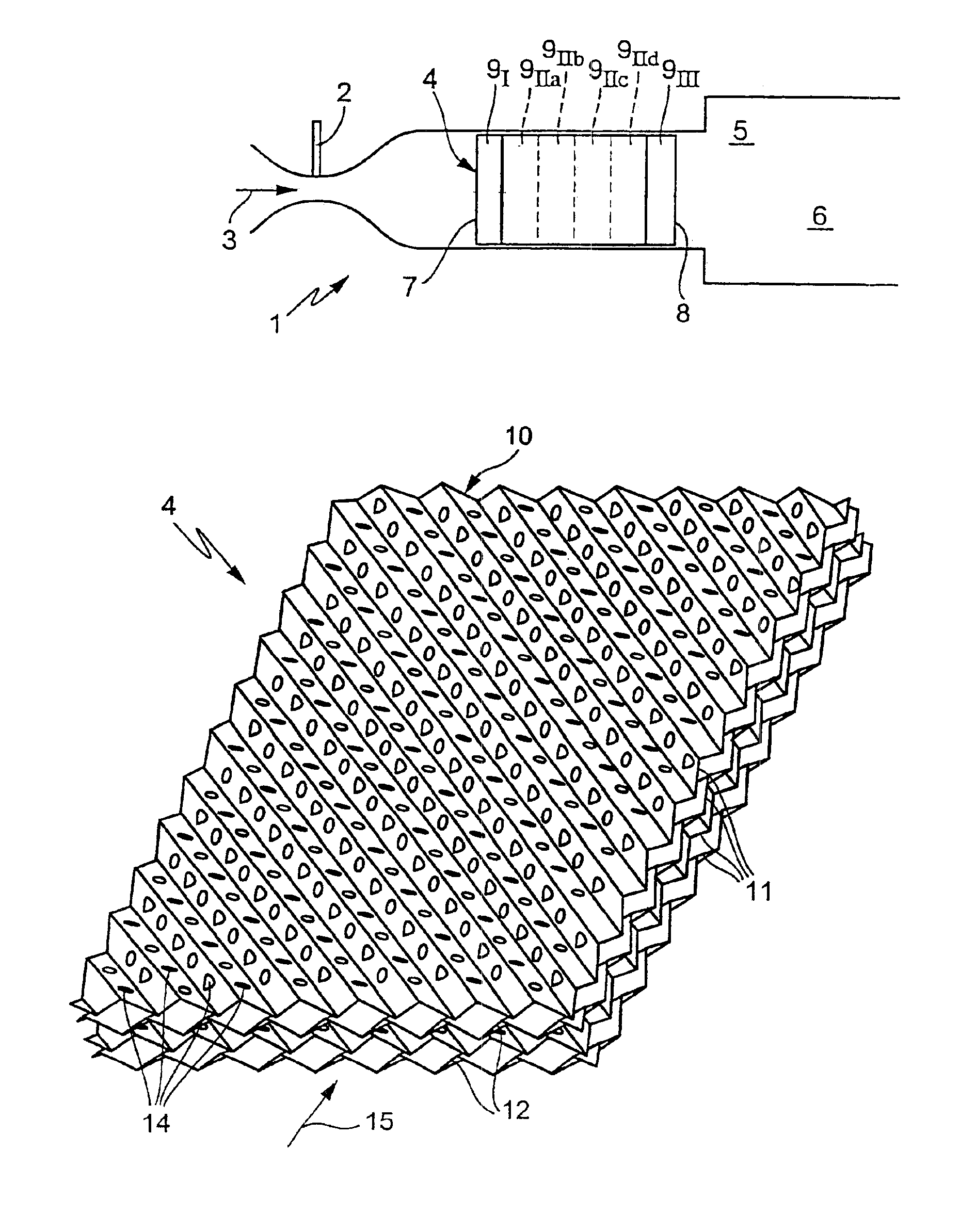
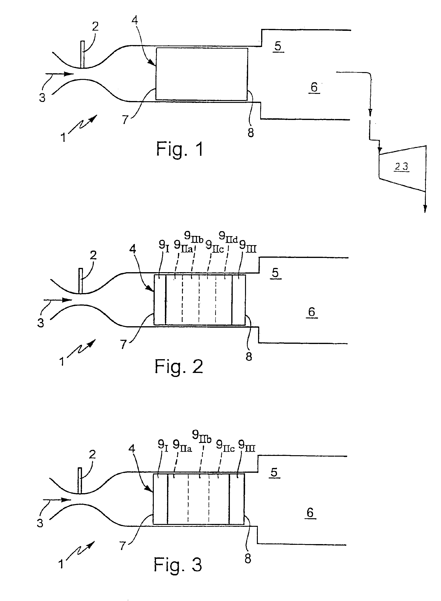
[0056]In a second embodiment according to FIG. 2, the inlet zone 9I is constructed catalytically inactive or inert and is equipped with turbulators (not shown here). Because of this measure, the inlet zone 9I acts as a static mixer that ensures homogeneous mixing of the gas stream 3 with the injected fuel. In the intermediate zone 9II, the carrier material is coated with a catalyst. The individual partial zones 9IIa to 9IId hereby may differ from each other with respect to catalytic activity and / or flow characteristics (e.g., turbulator density). In this intermediate zone 9II, the catalyst initiates the combustion reaction of the reaction mixture. By construction of the individual partial zones 9IIa to 9IId, this catalytically active part of the catalyzer structure 4 is specifically constructed so that a lower ignition temperature is achieved, whereby, the development of a homogeneous gas phase reaction within the catalyzer structure 4 is still avoided. In particular, one or the oth...

third embodiment

[0057] according to FIG. 3, the inlet zone 9I is designed so that between the adjoining channels a relatively intensive mixing that brings about a correspondingly intensive temperature compensation occurs. This can be realized in particular by means of correspondingly arranged turbulators. The inlet zone 9I is furthermore designed catalytically highly active so that the inlet zone 9I functions as an ignition zone. These characteristics of the inlet zone 9I can be realized in a particularly simple manner by using a woven metallic fiber material coated with the highly active catalyst as a carrier material. The intermediate zone 9II is also coated with a catalyst, whereby the intermediate zone 9II is designed with respect to a minimal pressure decrease, so that the risk that a homogeneous gas phase reaction is ignited within the catalyzer structure 4 is reduced. The intermediate zone 9II, for example, can be divided into several partial zones 9IIa to 9IIc that differ from each other wi...


PUM

PropertyMeasurementUnit
angleaaaaaaaaaa
catalytic activitiesaaaaaaaaaa
areaaaaaaaaaaa

Abstract

A catalytically operating burner with a catalyzer structure (4), useful in particular for a gas turbine system, has a heat-resistant carrier material (10) that forms the walls of several adjoining channels (13). The channels (13) pervade the catalyzer structure (4) in longitudinal direction and permit that a gaseous reaction mixture flows through the catalyzer structure (4). The walls are coated at least in part with a catalyst. In order to improve the catalytic conversion within the catalyzer structure (4), communicating openings (14) are constructed in the walls between an inlet end and an outlet end of the catalyzer structure (4). Adjoining channels (13) are able to communicate with each other through the communicating openings (14).

Description

[0001]This application is related and claims priority under 35 U.S.C. § 119 to German Patent Application Number 10119035.2, filed Apr. 18, 2001, entitled “Kalalytisch arbeitender Brenner”, by Timothy Griffin, Peter Jansohn, Verena Schmidt, and Dieter Winkler, the entire contents of which are incorporated by reference herein.FIELD OF THE INVENTION[0002]The invention relates to a catalytically operating burner.BRIEF DESCRIPTION OF THE RELATED ART[0003]U.S. Pat. No. 5,512,250 describes a catalyzer structure provided with a heat-resistant carrier material that forms the common walls of a plurality of adjoining channels. These channels pervade the catalyzer structure longitudinally and permit a gaseous reaction mixture to flow through the catalyzer structure. The walls are coated at least in part with a catalyst. In the known catalyzer structure, several channels are at least partially coated on their inside walls with the catalyst, while other channels are not coated with the catalyst a...

Claims


Application Information

Patent Timeline
Patent Type & Authority Patents(United States)
IPC IPC(8): F23C13/00F23R3/40F23R3/00B01J35/04F23D14/18
CPCF23R3/40F23C13/00
Inventor GRIFFIN, TIMOTHYJANSOHN, PETERSCHMIDT, VERENAWINKLER, DIETER
Owner ALSTOM TECH LTD
Why Eureka
Try Eureka