Multi-layer connector

a multi-layer connector and connector technology, applied in the direction of coupling device connection, two-part coupling device, electrical apparatus, etc., can solve the problems of large area inevitably occupied, time waste, and increased production costs without conforming, so as to reduce mold and material costs and minimize assembly time

Inactive Publication Date: 2005-05-03
TUNG MENG
View PDF3 Cites 10 Cited by
  • Summary
  • Abstract
  • Description
  • Claims
  • Application Information

AI Technical Summary

Benefits of technology

[0007]According to the aforesaid descriptions, to assemble the structure, the terminal main bodies are inserted into the terminal support, and the terminal front ends are inserted into the sliding channels of the plastic body. The signal nuts having different colors but identical dimensions are placed in the signal connecting openings at the front end of the plastic body, so as to substantially reduce mold and material costs. When the positioning pins at the lower portion of the plastic body are placed into the positioning openings at the lower portion of the terminal support, the fastening mechanisms of the terminal support and the plastic body are wedged and fastened with each other. The entire aforesaid structure is covered and fixed by the metal housing, and then altogether stabilized to pins of the circuit board for minimizing assembly time.

Problems solved by technology

However, when the aforesaid signal connectors are simultaneously installed at a same circuit board, a large area is inevitably occupied as a shortcoming.
Furthermore, it is necessary that parts of the signal connectors be individually manufactured, and duplications are also resulted to lead to wastage.
Consequently, time is wasted and production costs are elevated without conforming to market practicability and economical concerns.

Method used


Image

  • Multi-layer connector
  • Multi-layer connector
  • Multi-layer connector

Examples


Embodiment Construction

[0014]To better understand the structures, devices and characteristic of the invention, detailed descriptions of a preferred embodiment shall be given with the accompanying drawings below.

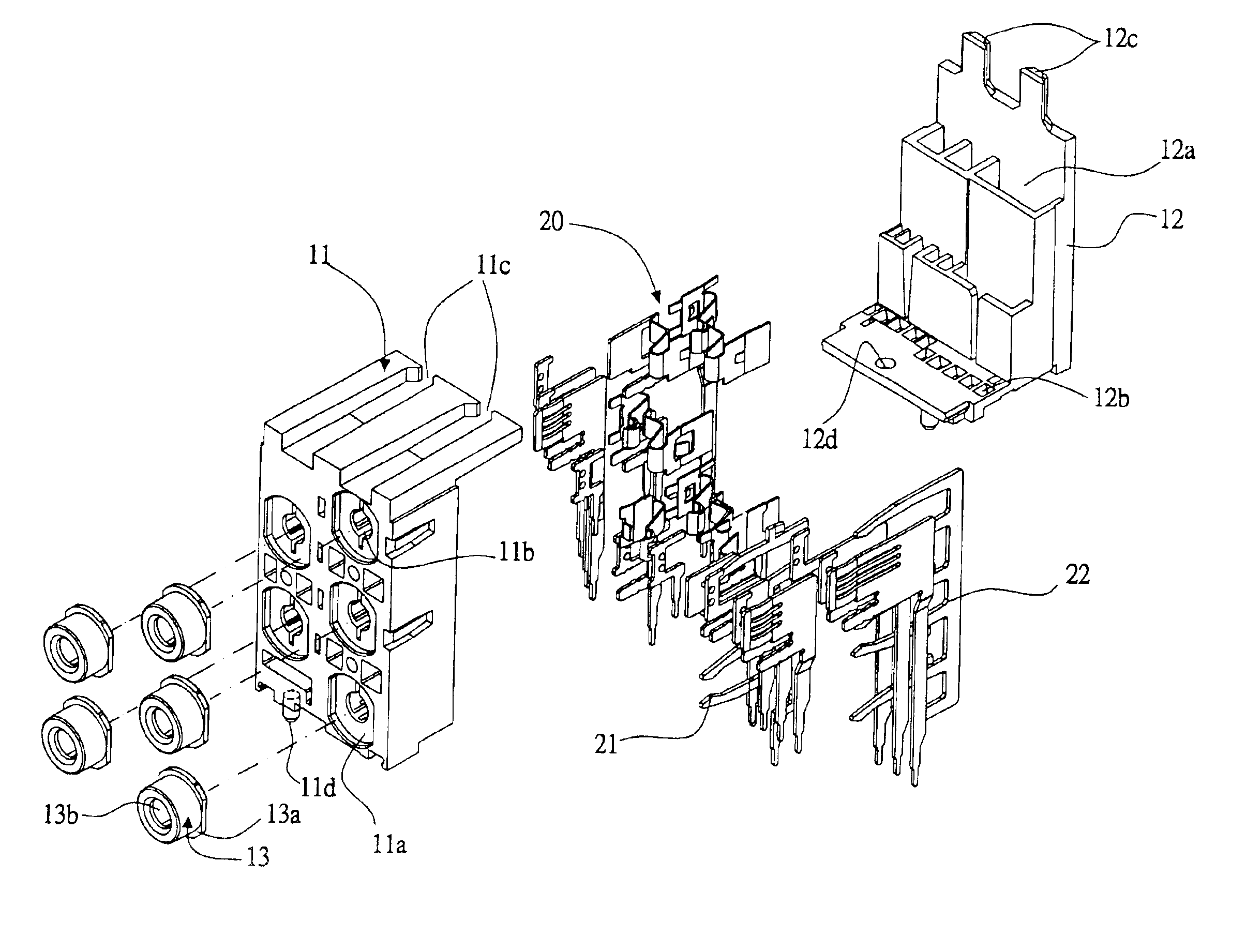
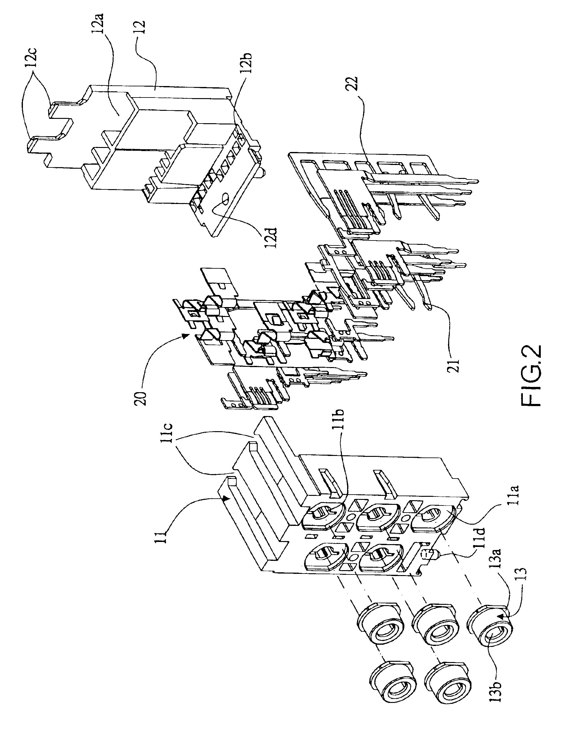
[0015]Referring to FIGS. 2, 3 and 4, a multi-layer connector 1 according to the invention comprises a plastic housing 10, terminals 20 and a metal housing 30. The plastic housing 10 is consisted of a plastic body 11 and a terminal support 12. Wherein, a front side of the plastic body 11 is disposed with five analog signal connecting openings 11a having identical dimensions. The analog signal connecting openings 1a have dimensions corresponding to those of signal connecting nuts 13, so as to accommodate the signal connecting nuts 13 therein. Each of the signal connecting nuts 13 is a hollow hat-shaped body, and has a skirt portion 13a at a periphery thereof and a round hole 13b at a center thereof for inserting signal terminals. A rear side of the plastic body 11 is provided with sliding channels 11...


PUM


Abstract

A multi-layer connector includes a plastic housing, terminals and a metal housing. The plastic housing is consisted of a plastic body and a terminal support, wherein the plastic body is provided with five integrated analog signal connecting openings at a front side thereof. To assemble the structure, the terminal main bodies are inserted into the terminal support, and the terminal front ends are placed into the sliding channels of the plastic body and are positioned by positioning pins at a lower portion of the plastic body and the terminal support. The aforesaid assembled structure is then covered by the metal housing, thereby offering a facilitated assembly as well as economized part and manufacturing costs.

Description

BACKGROUND OF THE INVENTION[0001](a) Field of the Invention[0002]The invention relates to a multi-layer connector, and more particularly, to a multi-layer connector for transmitting computer video and audio data and comprising a plastic housing, terminals and a metal housing. Wherein, the plastic housing is consisted of a plastic body and a terminal support.[0003](b) Description of the Prior Art[0004]Referring to FIG. 1 showing a prior signal connector installed to a computer equipment and for inputting and outputting analog audio data, because current computer equipments are generally provided with five-track functions including signal data input, microphone signal input, front speaker output, rear speaker output, and center and bass speaker output, a quantity of signal connectors required is also increased. The signal connectors are mostly arranged in stacks or arranged side by side. However, when the aforesaid signal connectors are simultaneously installed at a same circuit board...

Claims


Application Information

Patent Timeline
Patent Type & Authority Patents(United States)
IPC IPC(8): H01R13/502H01R13/514H01R13/506
CPCH01R12/727H01R13/506H01R23/6873H01R13/514H01R13/659
Inventor TUNG, MENG
Owner TUNG MENG
Why Eureka
Try Eureka