Synchronization control method and synchronization control device

a control method and control device technology, applied in the direction of programme control, electric controllers, total factory control, etc., can solve the problems of not being able the machining work or processing is not smooth at the junction between displacement data, and it is not possible to change the operation of the slave axis during the operation of the master axis. , to achieve the effect of reducing the size of displacement data and reducing the data volum

Inactive Publication Date: 2005-05-03
FANUC LTD
View PDF7 Cites 10 Cited by
  • Summary
  • Abstract
  • Description
  • Claims
  • Application Information

AI Technical Summary

Benefits of technology

[0010]It is an object of the present invention to provide a synchronization control method and device whereby a slave axis can be moved in any pattern in synchronization with a master axis, and whereby repetition of operations can be facilitated.
[0016]By adopting the foregoing composition, the present invention has the following beneficial effects.
[0018]Moreover, since an operation can be repeated for a stage, it is possible to reduce the data volume in cases containing sections where the same operation is repeated.
[0020]By enabling repetition and execution in desired stages, sections relating to the same operation can be concentrated in one place, and hence the size of the displacement data can be reduced.

Problems solved by technology

Therefore, the slave axis is simply able to repeat the same operation, and it is not possible to change the operation of the slave axis during operation, in accordance with the state of the machine, or to repeat a specific operation.
Moreover, although a sub-program method which calls up separate displacement data is commonly known, this method requires call-up processing, and therefore it has a drawback in that the pulses are interrupted at the junctions between different displacement data, and hence machining work or processing is not performed smoothly at junctions between displacement data.
As described above, in a conventional synchronization control method, since the displacement of the slave axis is synchronized with one revolution of the master axis, from the 0° angle of the master axis, it is not possible to change the operation of the slave axis during operation of the master axis, in other words, in accordance with the state of the machinery, or to repeat particular operations.
Furthermore, a problem occurs in that repeated sections must also be specified, and therefore the volume of data becomes very large.
There is also a method wherein repeated data is called up by a sub-program, or a method wherein the data is divided into a plurality of sets, but the data becomes fixed and cannot be adapted or used if the operational state is changed.

Method used


Image

  • Synchronization control method and synchronization control device
  • Synchronization control method and synchronization control device
  • Synchronization control method and synchronization control device

Examples


Embodiment Construction

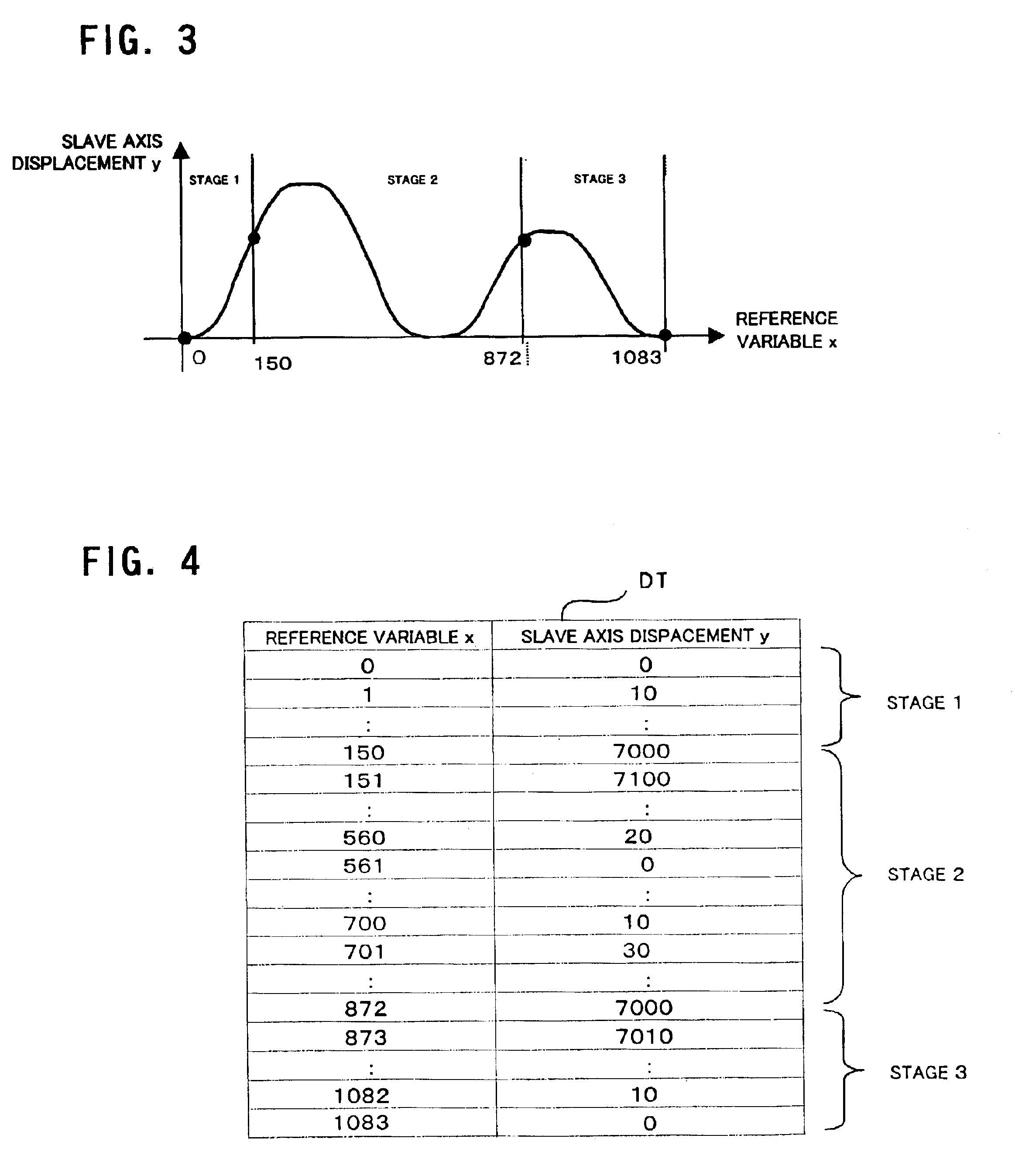
[0031]FIG. 3 illustrates the state of displacement of the slave axis in one embodiment of the present invention. In the present invention, a reference variable x, which associates the position of the master axis with the slave axis displacement, is provided, and the slave axis displacement y is set and registered as a function of this reference variable x. The slave axis displacement y corresponding to the reference variable x illustrated in FIG. 3 is stored in a data table DT as illustrated in FIG. 4.

[0032]Moreover, the position θ of the master axis (the position of the master axis being an angle between 0° and 360° (=0°), which is hereinafter called the phase), and the reference variable x is set in a linear relationship, whereby, for example, the reference variable x is 0 when the master axis phase θ is 0°, and the reference variable x is 50 when the master axis phase θ is 50°. In other words, there is a direct correlation between the master axis phase θ and the reference variabl...


PUM


Abstract

A reference variable having a linear relationship with the angular position of a master axis is set, and a correspondence between this reference variable and the displacement of a slave axis is stored in a data table. One execution stage is specified by setting a starting reference variable and an ending reference variable from this data table. A desired sequence is assigned to a plurality of execution stages thus specified. The reference variable corresponding to the angular position of the master axis is determined, slave axis displacement data corresponding to the reference variable is read out, and the slave axis is positioned in accordance with the position of the master axis on the basis of this displacement data.

Description

BACKGROUND OF THE INVENTION[0001]1. Field of the Invention[0002]The present invention relates to a synchronization control method and synchronization control device for synchronous driving of two or more movable axes, of an industrial device, construction device, or the like, in which synchronization control is performed.[0003]2. Description of the Prior Art[0004]In a conventional synchronization control method, one movable axis is taken as a master axis, and another movable axis is driven and controlled as a slave axis in synchronism with the master axis. In this case, the displacement of the slave axis is determined in accordance with the phase of the master axis, starting from a master axis phase of 0° until a complete revolution. Therefore, the slave axis is simply able to repeat the same operation, and it is not possible to change the operation of the slave axis during operation, in accordance with the state of the machine, or to repeat a specific operation.[0005]FIG. 1 is an e...

Claims


Application Information

Patent Timeline
Patent Type & Authority Patents(United States)
IPC IPC(8): G05B19/19G05D3/00G05D3/12
CPCG05B19/19G05B2219/42186G05B2219/43174G05B2219/50234G05B2219/50218G05B2219/50233G05B2219/50216Y02P90/02
Inventor FUJIBAYASHI, KENTAROHISHIKAWA, TETSUOIDEI, TAKASHI
Owner FANUC LTD
Why Eureka
Try Eureka