Test system and test contactor for electronic modules

a test system and contactor technology, applied in the field of test system, test contactor and test method for testing electronic modules, can solve the problems of more expensive operation and maintenan

Inactive Publication Date: 2005-05-03
MICRON TECH INC
View PDF34 Cites 25 Cited by
  • Summary
  • Abstract
  • Description
  • Claims
  • Application Information

AI Technical Summary

Benefits of technology

[0019]In each of the embodiments, the test contactors are designed to electrically engage the terminal contacts with a zero insertion force (ZIF) on the module. Movement of the test contactors into the terminal contacts can be provided by cams, hydraulic cylinders, motors or any suitable mechanical actuator. In addition, the test contactors are designed to penetrate, or to scrub, the terminal contacts during electrical engagement, and also to help retain the module on the interface board. Further, the test contactors are designed for quick engagement and disengagement with the terminal contacts, and are designed to provide a relatively short electrical path to the terminal contacts.

Problems solved by technology

The socket test system 11S can therefore damage the module 10, or the terminal contacts 14 on the module 10, and can be more expensive to operate and maintain.

Method used


Image

  • Test system and test contactor for electronic modules
  • Test system and test contactor for electronic modules
  • Test system and test contactor for electronic modules

Examples


first embodiment

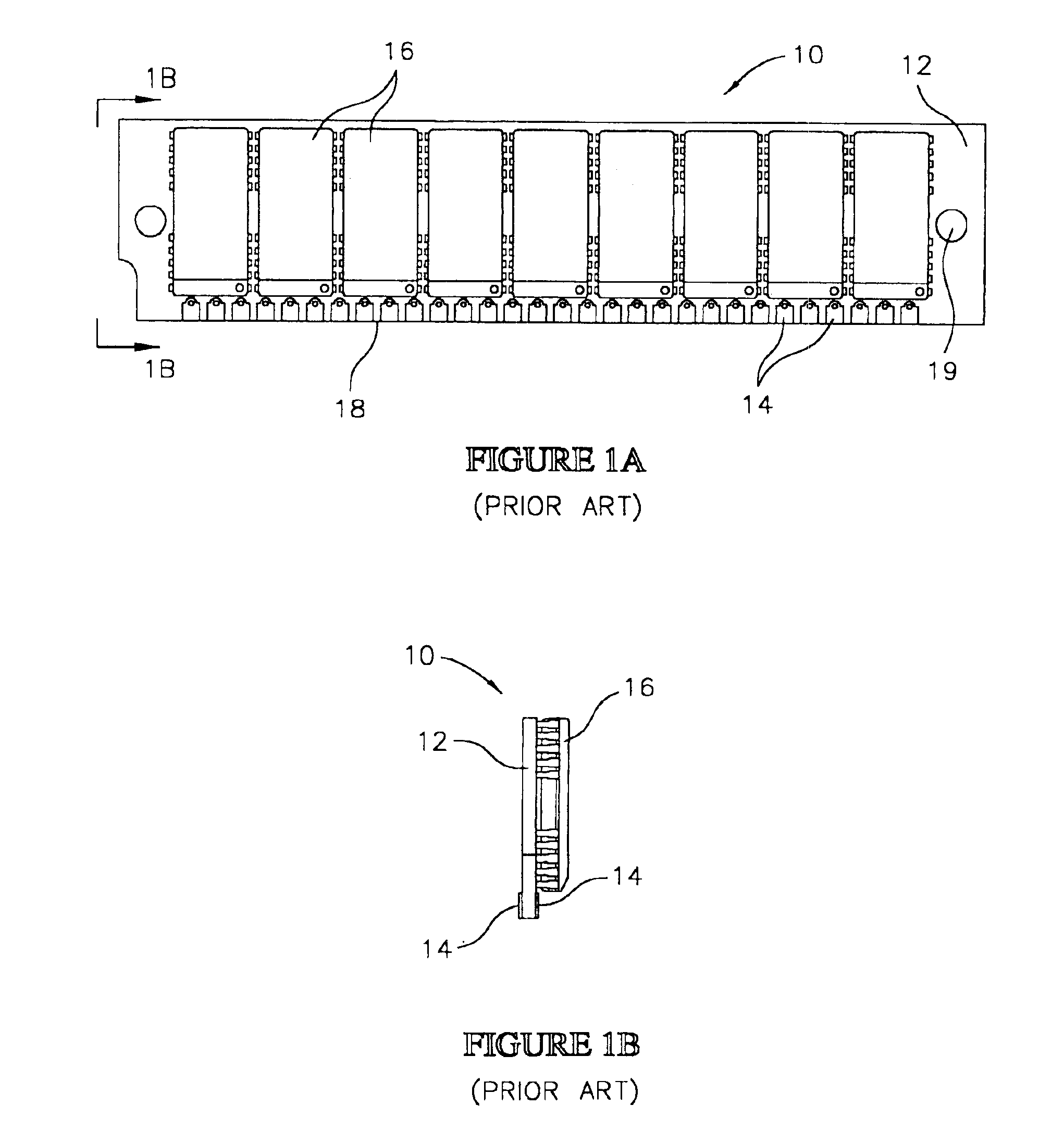
[0038]Referring to FIGS. 2A and 2B, a pass through test system 20 constructed in accordance with the invention, and configured to test electronic modules 10, is illustrated. The test system 20 includes an interface board 22, and a plurality of test contactors 24 rotatably mounted to the interface board 22 configured to make temporary electrical connections with the terminal contacts 14 on the module 10.

[0039]As used herein, the term “pass through test system” means a test system in which temporary electrical connections are made with the terminal contacts 14 on the module 10 with a “zero insertion force”. As used herein, the term “zero insertion force” means that no forces are being exerted on the module 10 to move the test contactors 24 in making the temporary electrical connections.

[0040]The interface board 22 is configured to support the module 10 on the edge 18 thereof substantially as shown. The interface board 22 is configured for mounting to an automated or manual pass throug...

second embodiment

[0050]Referring to FIGS. 3A and 3B, a pass through test system 20A constructed in accordance with the invention is illustrated. The test system 20A includes an interface board 22A, and a plurality of test contactors 24A slidably mounted to the interface board 22A. The interface board 22A is configured to support the module 10 on the edge 18 thereof substantially as shown. In addition, the interface board 22A is configured for mounting to an automated or manual pass through test handler, substantially as previously described. Further, the interface board 22A includes contact pads 26A, and conductors 30A in electrical communication with the test circuitry 28 substantially as previously described.

[0051]The test contactors 24A are configured to establish electrical communication between the terminal contacts 14 on the module 10, and the contact pads 26A on the interface board 22A, with a zero insertion force on the module 10. The test contactors 24A include a slidable base 32A, and a pl...

third embodiment

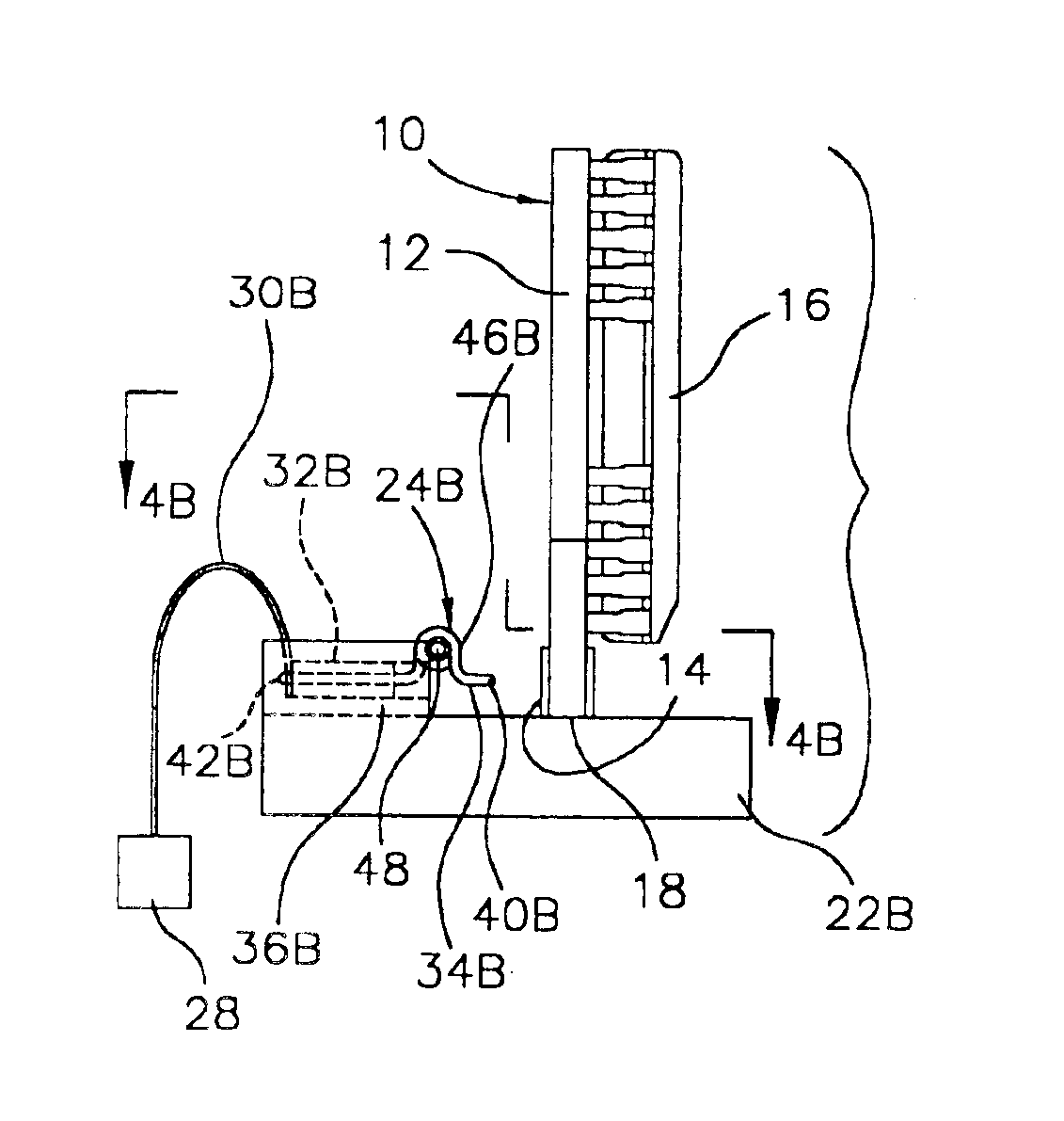
[0056]Referring to FIGS. 4A and 4B, a pass through test system 20B constructed in accordance with the invention is illustrated. The test system 20B includes an interface board 22B, and a plurality of test contactors 24B slidably mounted to the interface board 22B. The interface board 22B is configured to support the module 10 on the edge 18 thereof substantially as shown. In addition, the interface board 22B is configured for mounting to an automated or manual pass through test handler, substantially as previously described.

[0057]The test contactors 24B are configured to establish electrical communication between the terminal contacts 14 on the module 10, and the test circuitry 28 with a zero insertion force being exerted on the module 10. The test contactors 24B include a slidable base 32B, and coiled spring contacts 34B on the base 32B. In this embodiment a flex circuit 30B is in electrical communication with the spring contacts 34B. The flex circuit 30B is designed to move with t...


PUM


Abstract

A pass through test system for testing an electronic module includes an interface board, and test contactors movably mounted to the interface board for electrically engaging terminal contacts on the module with a zero insertion force on the modules. The interface board is configured for mounting to an automated or manual pass through test handler in electrical communication with test circuitry. In a first embodiment the interface board includes test pads in electrical communication with the test circuitry, and rotatable test contactors having spring contacts configured to simultaneously engage the test pads and the terminal contacts on the module. In a second embodiment the interface board includes test pads in electrical communication with the test circuitry, and slidable test contactors having beam leads configured to simultaneously engage the test pads and the terminal contacts on the module. In a third embodiment the test contactors are slidably mounted to the interface board, and include coiled spring contacts in electrical communication with a flex circuit. A test method includes the steps of: providing the test contactors, electrically engaging the terminal contacts on the module with a zero insertion force using the test contactors, and then applying test signals through the test contactors and the terminal contacts to the module.

Description

CROSS REFERENCE TO RELATED APPLICATIONS[0001]This application is a division of Ser. No. 10 / 236,276, filed Sep. 6, 2002, U.S. Pat. No. 6,727,715 B2, which is a division of Ser. No. 09 / 650,161 filed Aug. 28, 2000, U.S. Pat. No. 6,483,329 B1.FIELD OF THE INVENTION[0002]This invention relates generally to the testing of electronic modules, and more particularly to a test system, a test contactor and a test method for testing electronic modules.BACKGROUND OF THE INVENTION[0003]Electronic modules, such as semiconductor memory modules, multi chip modules, semiconductor carriers, semiconductor packages, and microprocessors are routinely tested during manufacture. The modules include terminal contacts in electrical communication with the electronic devices contained on the modules. For performing various test procedures on the modules, temporary electrical connections are made to the terminal contacts.[0004]One type of prior art electronic module 10, which is illustrated in FIGS. 1A and 1B, ...

Claims


Application Information

Patent Timeline
Patent Type & Authority Patents(United States)
IPC IPC(8): G01R1/04G01R1/02G01R1/073G01R31/02G01R31/28
CPCG01R1/0408G01R31/2889G01R1/07385G01R1/0416
Inventor CRAM, DANIEL P.
Owner MICRON TECH INC
Why Eureka
Try Eureka