Electroluminescent device with sufficient luminous power and driving method thereof

a technology of luminous power and electric motor, applied in the direction of static indicating devices, instruments, printing, etc., can solve the problem of complicated data electrode driver

Inactive Publication Date: 2005-05-03
DENSO CORP
View PDF6 Cites 2 Cited by
  • Summary
  • Abstract
  • Description
  • Claims
  • Application Information

AI Technical Summary

Benefits of technology

[0018]According to another aspect of the present invention, a method for driving an EL device and a method for driving a printer head of the present invention include applying a driving voltage to both sides of a plurality of EL elements through a control unit to cause the plurality of EL elements to emit light several times per driving cycle.

Problems solved by technology

As a result, to withstand a high surge voltage, the data electrode driver is complicated.

Method used


Image

  • Electroluminescent device with sufficient luminous power and driving method thereof
  • Electroluminescent device with sufficient luminous power and driving method thereof
  • Electroluminescent device with sufficient luminous power and driving method thereof

Examples


first embodiment

[0055](First Embodiment)

[0056]In the first embodiment, a dot matrix type EL display device (EL display device) will now be described with reference to FIGS. 1-6.

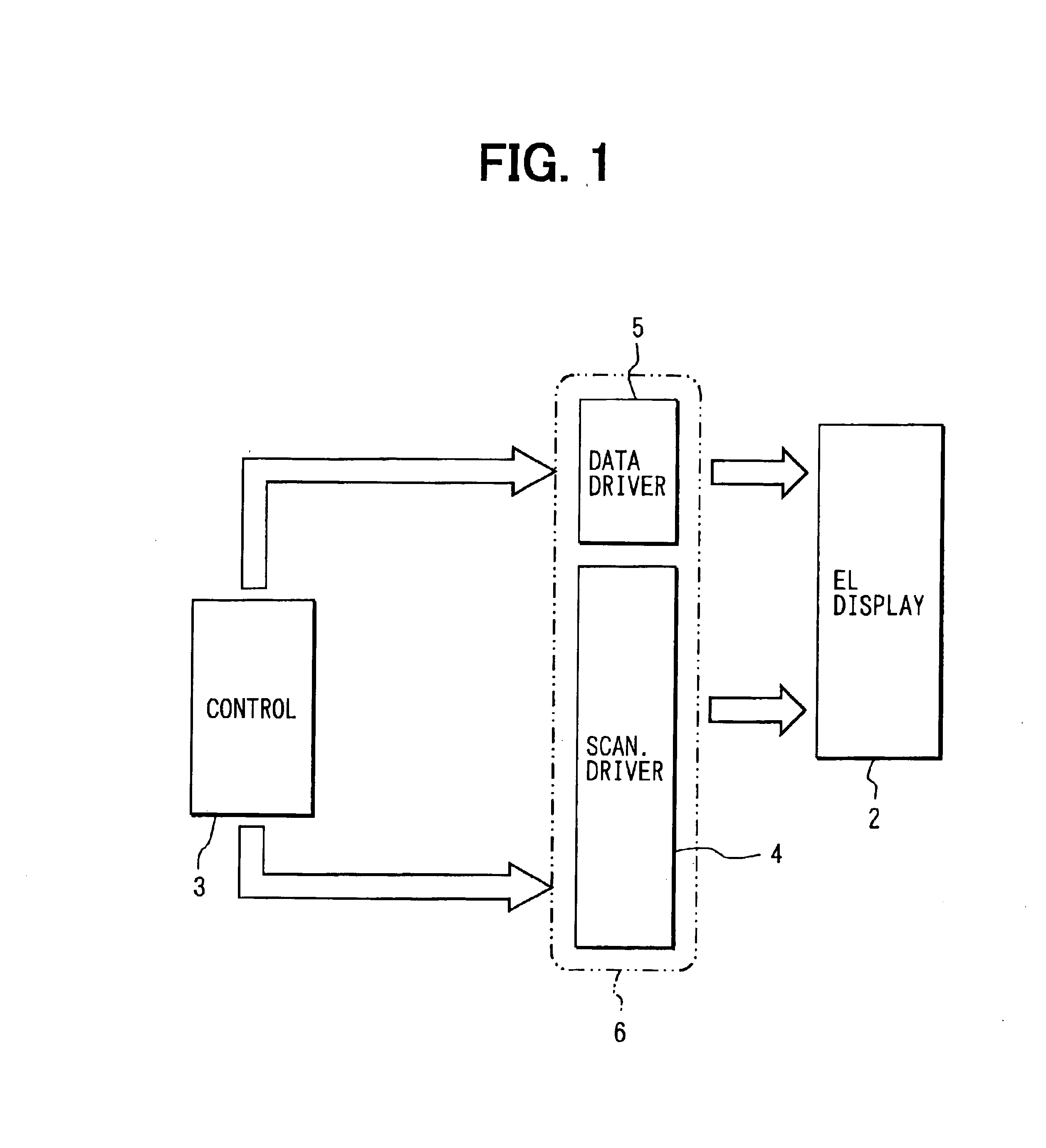
[0057]In FIG. 1, an EL display 2 is controlled by a control unit 3. Specifically, the control unit 3 outputs control signals to a scanning electrode driver (driving circuit) 4 and a data electrode driver (driving circuit) 5 to control the EL display 2.

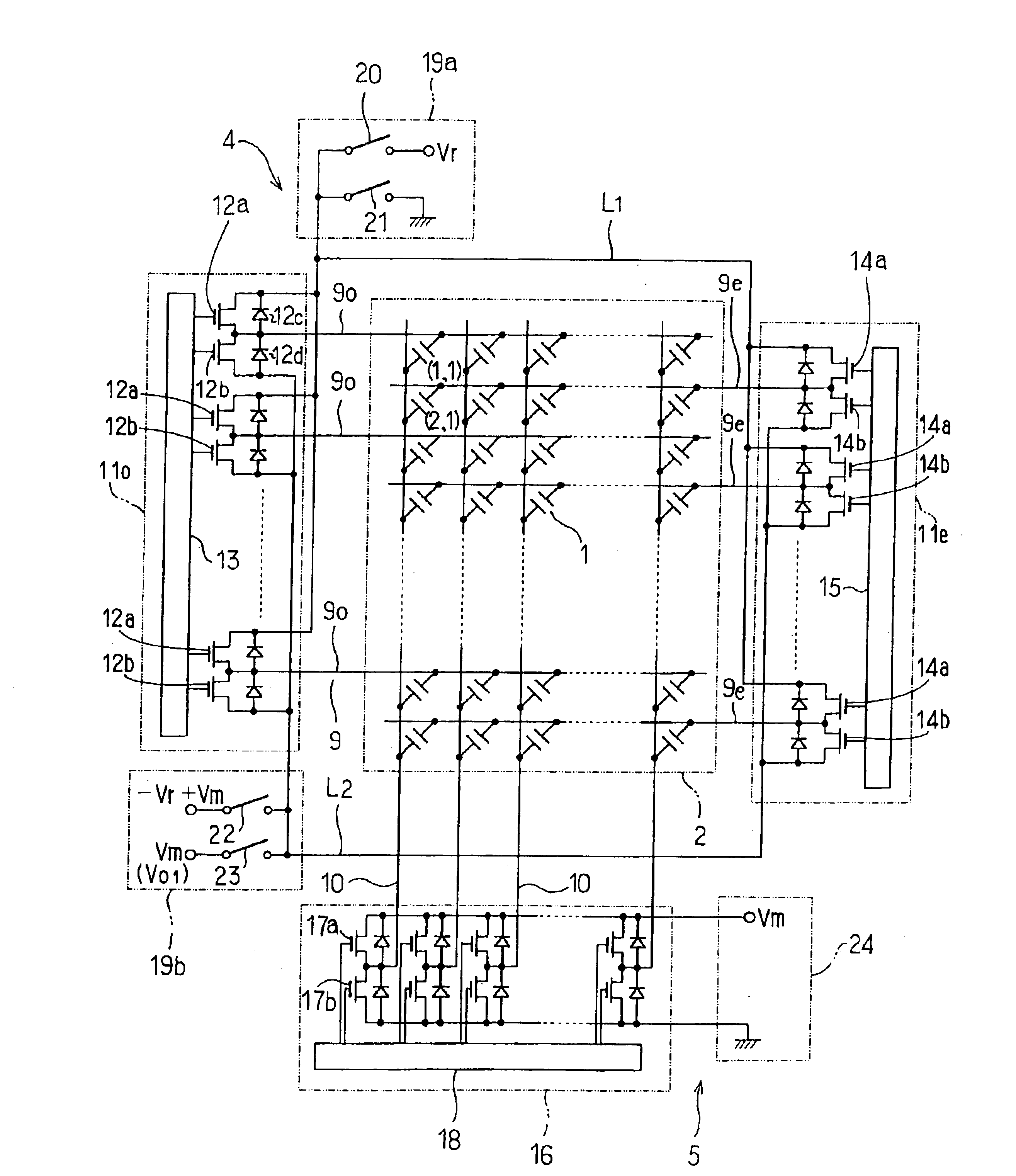
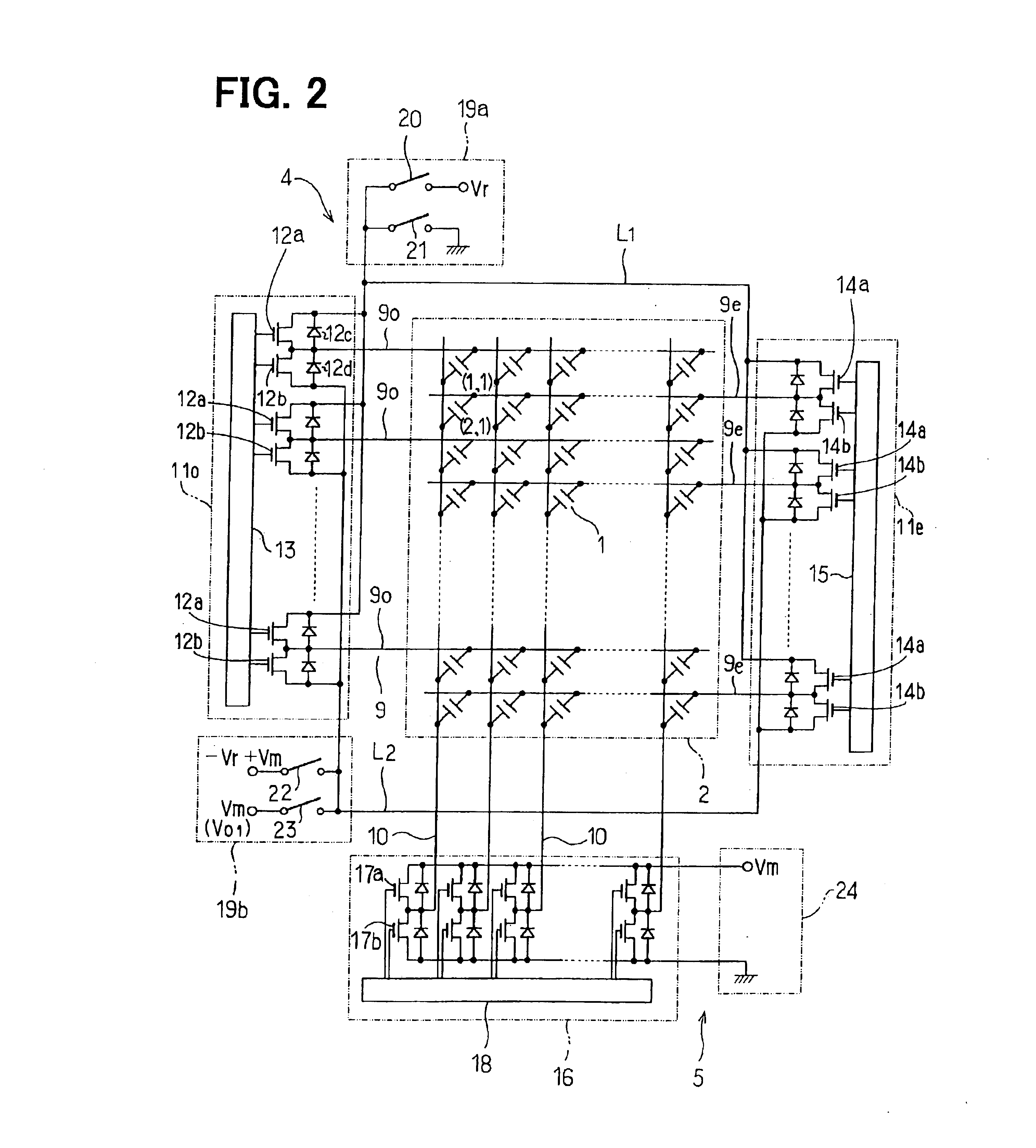
[0058]FIG. 2 illustrates a specific electrical circuit of the EL display device 2, scanning electrode driver 4 and the data electrode driver 5. The EL display 2 is configured by a plurality of EL elements 1 arranged in matrix form. Specifically, a plurality of scanning electrodes 9 and a plurality of data electrodes 10 is respectively arranged in grid form to form a matrix. Each of the intersections formed by the scanning electrodes 9 and the data electrodes 10 corresponds to each of the EL elements 1, thereby forming a simple dot matrix type display configuration. In this conf...

second embodiment

[0094](Second Embodiment)

[0095]In the second embodiment shown in FIGS. 7 to 12, a printer head of a luminescent printer is described according to another embodiment of the present invention. As shown in these figures, the printer head is configured with EL elements 1 of the type described in the first embodiment.

[0096]FIG. 7 is a schematic view showing main portions of the luminescent printer, and FIG. 8 is oblique perspective view of the printer head 60 and a light sensitive drum (a light sensitive portion) 31 illustrated in FIG. 7.

[0097]The light sensitive drum 31 is configured to rotate clockwise in FIG. 7. The light sensitive drum 31 is charged with negative charges through a charge portion 32, and then the surface thereof is exposed through an EL element array 33 and a Selfoc lens 34 shown in FIG. 8, which corresponds to the printer head 60, so as to print image data defined with respect to print objects. Therefore, in a part of the surface of the light sensitive drum 31 at whi...

third embodiment

[0117](Third Embodiment)

[0118]In the third embodiment shown in FIGS. 13 and 14, a printer head of a luminescent printer according to a third embodiment of the present invention is described. As shown in FIGS. 13 and 14, in the third embodiment, the printer head having an EL element array 33 configured by EL elements 1 is modified with respect to that in the second embodiment. That is, a capacitor 46 is disposed between a scanning electrode driver 43 and data electrode drivers 44.

[0119]According to the printer head of the third embodiment, the scanning electrode driver 43 and the data electrode drivers 44 are associated by the capacitor 46. Therefore, when a driving voltage waveform illustrated in FIG. 15 is applied to the EL elements 1, a voltage corresponding to a differential waveform with sharp peaks at each of rise and fall times of the driving voltage waveform is applied to the scanning electrode 9 as illustrated in FIG. 15. Since the EL elements 1 emit light at each of the ris...


PUM


Abstract

An EL device includes a control unit that controls a driving circuit so that a plurality of EL elements emits light several times per driving cycle. Specifically, when a driving voltage is applied to the plurality of EL elements, the plurality of EL elements emits several times per driving cycle. As a result, since the amount of light integrated per time increases, the plurality of EL elements obtains high luminous power even if a plurality of El elements having a very short emission decay time is used.

Description

CROSS REFERENCE TO RELATED APPLICATIONS[0001]This application is based upon and claims the benefit of Japanese Patent Application No. 2002-072220 filed on Mar. 15, 2002, No. 2002-072274 filed on Mar. 15, 2002 and No. 2002-257668 filed on Sep. 3, 2002, the contents of which are incorporated herein by reference.FIELD OF THE INVENTION[0002]The present invention relates generally to electro-luminescent (EL) devices with EL elements having an short emission decay time and driving method thereof.BACKGROUND OF THE INVENTION[0003]JP-A-9-54566 discloses a display with EL elements having a phosphor made of ZnS:Mn. However, such El elements only emit an umber color light so that the EL device cannot be used as a display. Accordingly, other displays with EL elements emitting other colors are now being developed.[0004]As for printer technology, a printer head having LEDs as a light source is used for an LED printer. However, because light emitted from respective LEDs is imbalanced, the printing ...

Claims


Application Information

Patent Timeline
Patent Type & Authority Patents(United States)
IPC IPC(8): B41J2/45
CPCB41J2/45
Inventor INOUE, TAKASHIKATAYAMA, MASAYUKIHATTORI, YUTAKASUZUKI, HIROTAKAOSADA, MASAHIKOYAMAMOTO, YASUOUCHIDA, TOMOYA
Owner DENSO CORP
Why Eureka
Try Eureka