Loudspeaker suspension

a technology of loudspeaker and suspension, which is applied in the direction of transducer diaphragm, electrical transducer, instruments, etc., can solve the problem that the objective cannot be fully achieved in the practi

Inactive Publication Date: 2005-05-10
HARMAN INT IND INC
View PDF9 Cites 26 Cited by
  • Summary
  • Abstract
  • Description
  • Claims
  • Application Information

AI Technical Summary

Benefits of technology

[0008]In operation the axial movement of the diaphragm causes hoop stresses in the suspension. In a conventional suspension these stresses must be accommodated by the suspension stretching circumferentially (peripherally). The suspension material is stiff in tension, and thus the compliance of the suspension is reduced and the ability of the speaker to extend axially is compromised. In the present invention, advantage is taken of the fact that the material is much less stiff in bending to achieve an adequately-compliant suspension. In a preferred form, the suspension material is of corrugated or concertina-like form around the periphery of the surround so that it may expand and contract easily in the peripheral direction.

Problems solved by technology

This objective cannot be fully achieved in practice.
In particular it can be impeded by the flexible surround failing to permit adequate axial movement of the edge of the cone at low frequencies, or by it having an axial stiffness which varies with axial displacement, or by the surround deforming asymmetrically (buckling) upon axial displacement.

Method used


Image

  • Loudspeaker suspension
  • Loudspeaker suspension
  • Loudspeaker suspension

Examples


Embodiment Construction

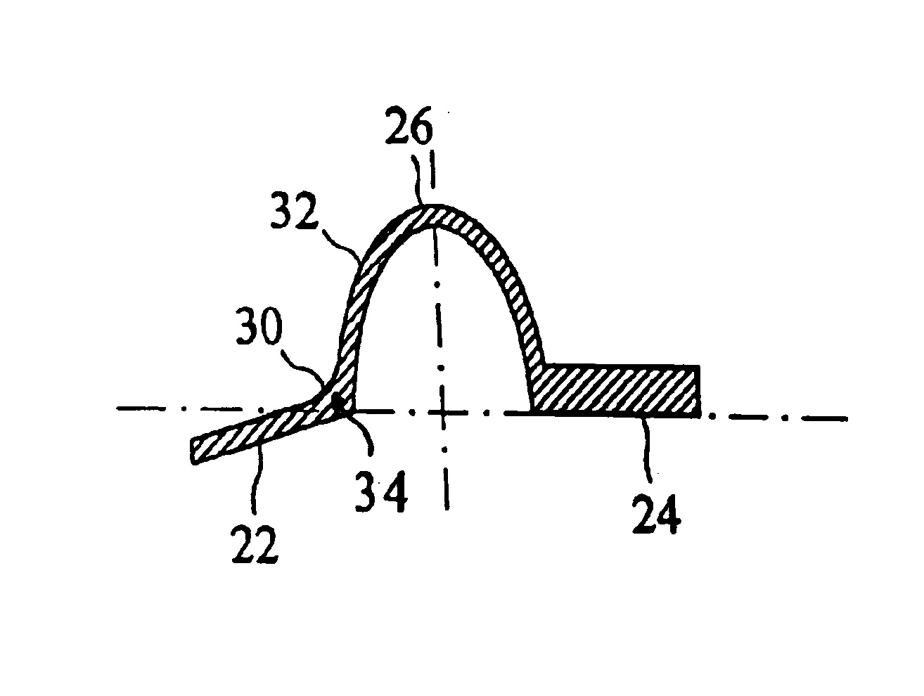
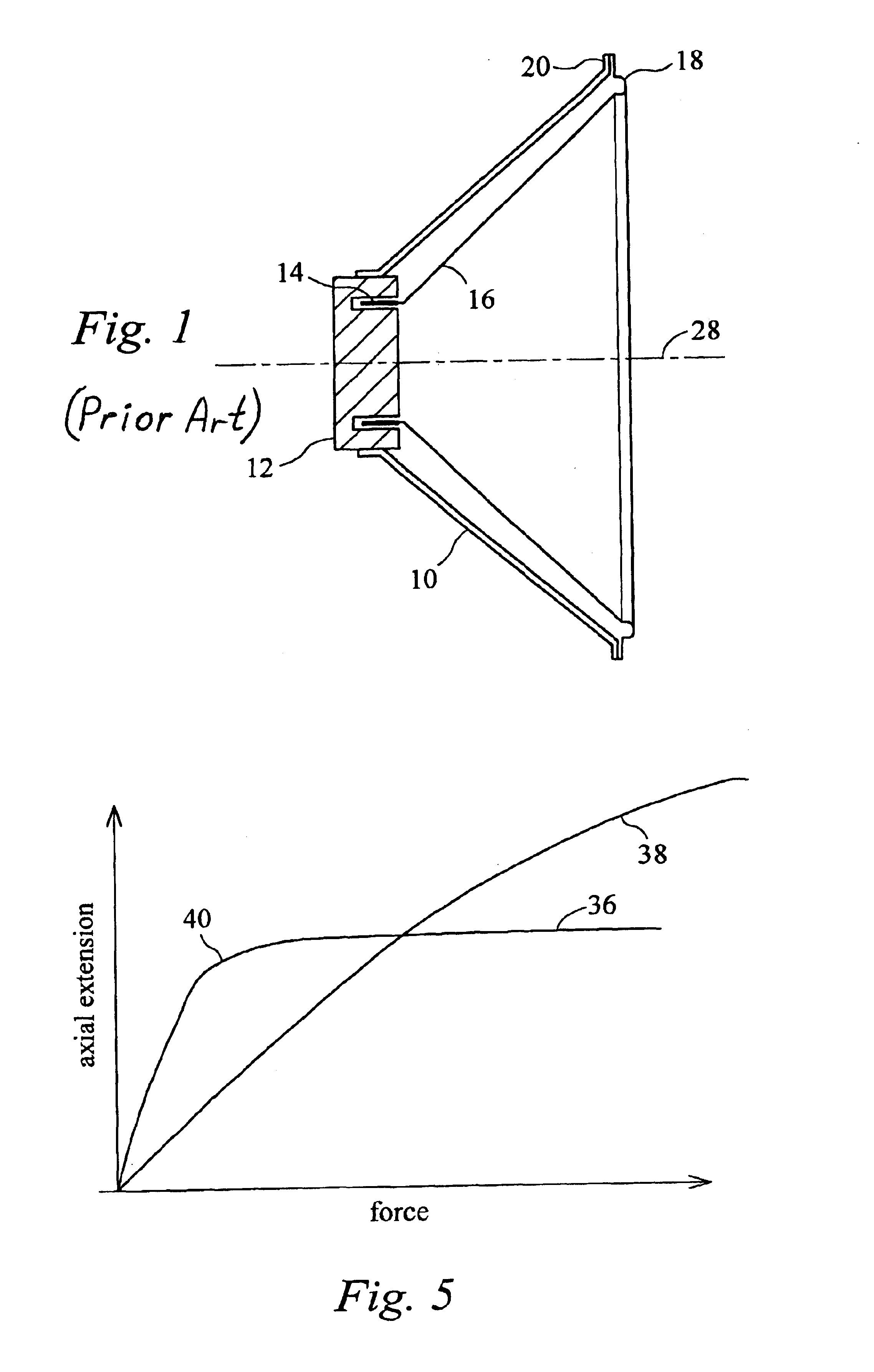
[0031]In FIG. 1 a typical loudspeaker comprises a frame or chassis 10 supporting a permanent magnetic circuit 12 having a gap wherein a voice coil 14 of a cone 16 is received. The basal edge of the cone terminates in a surround or suspension 18 the outer edge of which is fixed to a mounting ring 20 of the frame.

[0032]The cone 16, here circular in shape, is typically molded from a relatively stiff plastics material such as ADSTIFF (TM) polypropylene and is as stiff as a light as possible so as to respond faithfully to an electroacoustic driving signal applied to the voice coil.

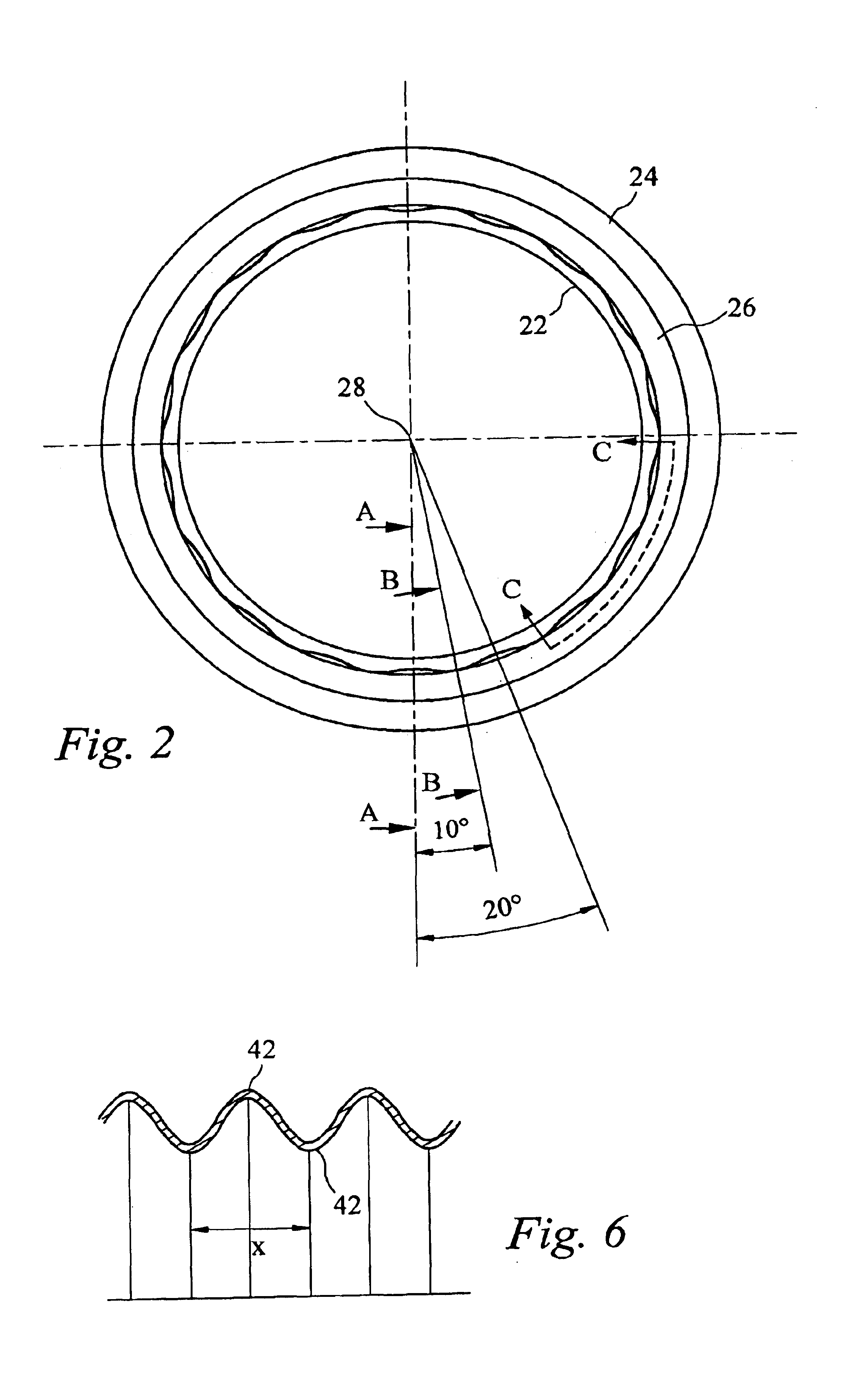
[0033]Referring to FIGS. 2, 3 and 4 the surround 18 of this invention is of a softer and more flexible material than the cone, for example a mixture of polypropylene eg. ADFLEX (TM) and an elastomer, eg. SARLINK (TM), compatible with the cone material so that it can be overmoulded, ultrasonically welded thermally bonded or glued to it, a radially inner flange 22 being provided for this purpose. A radially outer...


PUM


Abstract

An annular surround for a loudspeaker cone wherein a radial cross-section of the surround varies around the circumferential extent of the surround, so as to accommodate peripheral expansion or contraction of the surround by bending. Thus a trough shaped cross-section of the surround may vary sinusoidally with angle around the polar axis of the surround between a semicircular and semielliptical cross-section. The trough section may bland to an adjacent portion of the surround by a fillet which also varies sinusoidally in cross-section in phase with the variation of the trough.

Description

BACKGROUND OF THE INVENTION[0001]This invention relates to a loudspaker suspension and to a loudspeaker cone or other diaphragm comprising a suspension.[0002]A loudspeaker typically comprises a relatively rigid cone driven by a voice coil at the apex of the cone, the cone being supported around its basal edge from a ring shaped fixed frame by a relatively flexible suspension. Ideally the cone responds identically at all frequencies within its operating range so that input audio signals are converted to sound waves without change in relative power or phase, and without generation of harmonics. Thereby distortion and coloration can be avoided.[0003]This objective cannot be fully achieved in practice. In particular it can be impeded by the flexible surround failing to permit adequate axial movement of the edge of the cone at low frequencies, or by it having an axial stiffness which varies with axial displacement, or by the surround deforming asymmetrically (buckling) upon axial displac...

Claims


Application Information

Patent Timeline
Patent Type & Authority Patents(United States)
IPC IPC(8): H04R7/00H04R7/22
CPCH04R7/22H04R2307/207
Inventor POCOCK, NICHOLASPETTMAN, SIMON YORICK
Owner HARMAN INT IND INC
Why Eureka
Try Eureka