Controlled motion system having an improved track configuration

a technology of motion system and track configuration, which is applied in the direction of program control, total factory control, instruments, etc., can solve the problems of high required motor force, position error, cogging, etc., and achieve the effect of reducing mechanical complexity, increasing process speed and flexibility, and reducing cos

a technology of motion system and track configuration, which is applied in the direction of program control, total factory control, instruments, etc., can solve the problems of high required motor force, position error, cogging, etc., and achieve the effect of reducing mechanical complexity, increasing process speed and flexibility, and reducing cos

US20140331888A1Active Publication Date: 2014-11-13ROCKWELL AUTOMATION

Image

  • Controlled motion system having an improved track configuration
  • Controlled motion system having an improved track configuration
  • Controlled motion system having an improved track configuration

Examples


Embodiment Construction

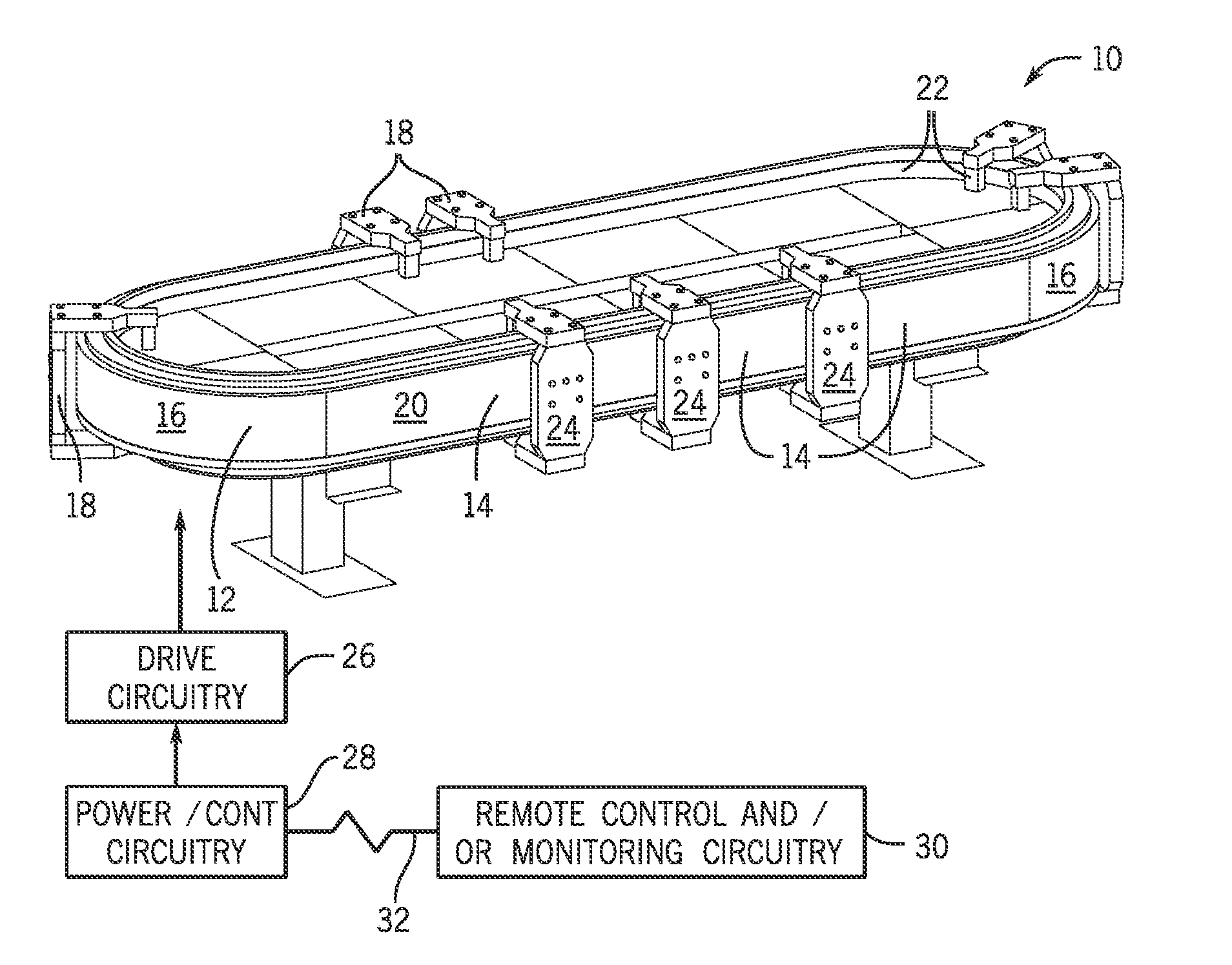
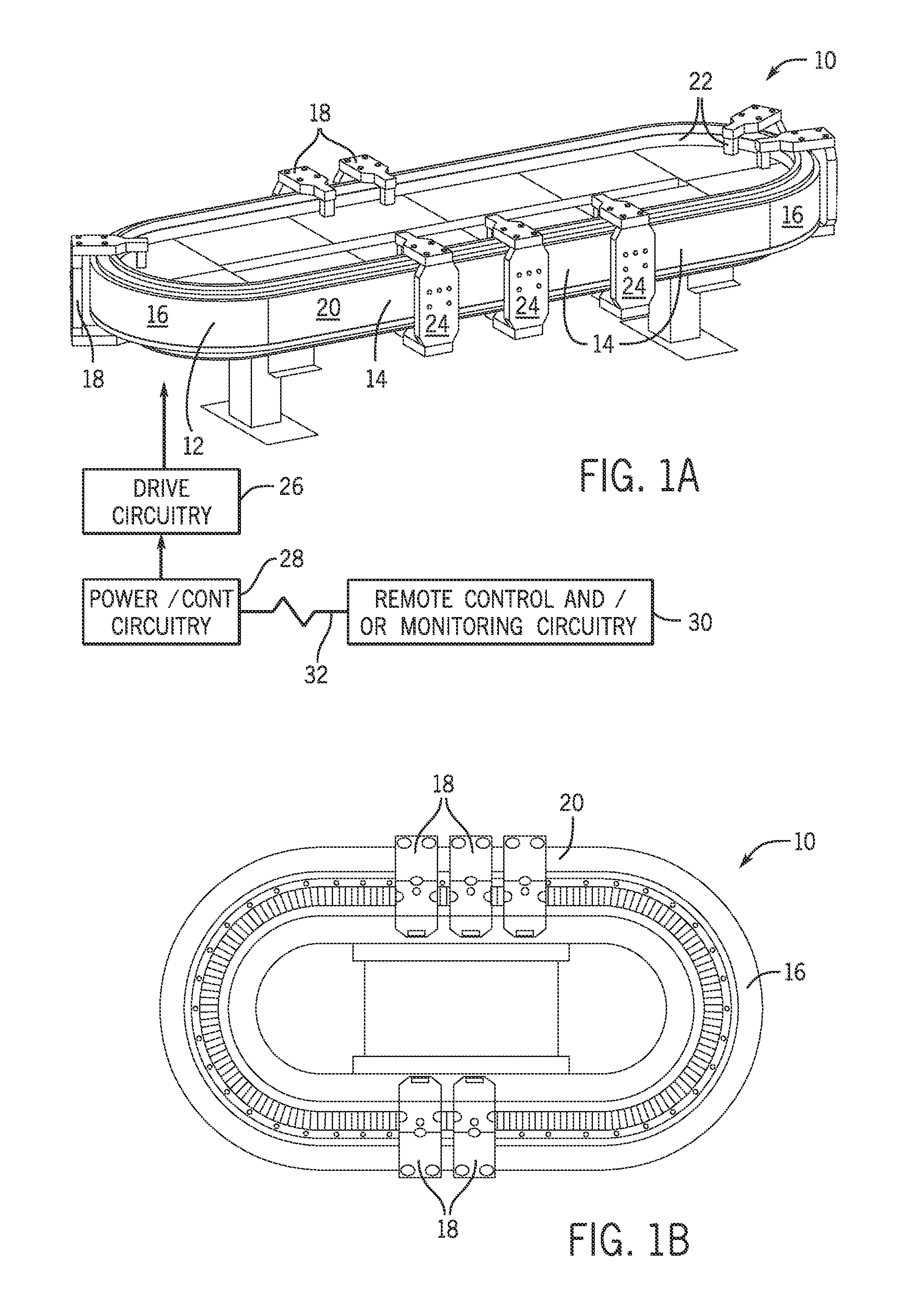
[0040]Turning now to the drawings, and referring first to FIG. 1A, a transport system 10 as illustrated for moving articles or products around a track 12. As will be appreciated by those skilled in the art, in many applications, the transport system will be configured to inter-operate with other machines, robots, conveyers, control equipment, and so forth (not separately shown) in an overall automation, packaging, material handling or other application. The transport system itself generally comprises a “linear motorsystem as discussed below, in which the moving components are positioned, accelerated, decelerated, and generally moved under the influence of controlled magnetic and electromagnetic fields. In the illustrated embodiment, the track 12 comprises straight track modules 14 and curved track modules 16. These modules may be generally self-contained and mountable in various physical configurations, such as the oval illustrated in FIG. 1A. It should be noted that other configu...


PUM


Abstract

A transport system comprising linear motor modules utilized both straight and curved track modules, with movers displaced on the track modules by control of power applied to coils of the modules. Curved track modules have modified spline geometries to provide desired acceleration and jerk characteristics. The modified spline geometries may be defined by more than one generators, such as an equation generator and a spline fit between the equation-generated segment and one or more constrained points or locations. The curved track modules may be divided into 180 degree modules, or may be reduced to 90 degree, 45 degree or other fractional arcs to provide for modular assembly, mirror-image geometries and motion profiles, and the like. The system may be adapted to provide improved motion characteristics based on modification of a conventional spline geometry.

Description

CROSS REFERENCE TO RELATED APPLICATIONS[0001]This application is a Non-Provisional patent application of U.S. Provisional Patent Application No. 61 / 821,450, entitled “Controlled Motion System Having an Improved Track Configuration”, filed May 9, 2013, which is herein incorporated by reference.BACKGROUND[0002]The present invention is directed to linear motor and transport systems, and, more particularly, to arrangements for providing curves and directional transition modules in such systems.BRIEF DESCRIPTION[0003]Transport systems, such as controlled motion systems utilizing linear drives, are used in a wide variety of processes (e.g. packaging, assembly automation, processes involving use of machine tools, etc.) and provide the advantage over conventional rotary drive systems of increasing both the speed and the flexibility of the process. In particular, linear motors operate as magnetic drives creating a changing magnetic field to directly transport the axis or transport element al...

Claims


Application Information

Patent Timeline
13 Nov 2014
Publication
US20140331888A1
IPC
B60L13/00; B60L13/04
CPC
B60L13/006; B60L13/04; B65G54/02; G05B19/4189; H02K41/03; Y02P90/02; A63G21/04
Inventors
WERNERSBACH, GLEN C.; KOEPPEL, MARC D.