Automobile assembly

a technology for automobiles and components, applied in the direction of stationary conduit assemblies, domestic objects, understructures, etc., can solve the problems of not considering the use of adhesives to bond reinforcing components, the design and structural effectiveness of reinforcing components is reduced, and the design and structural effectiveness of reinforcing components are reduced. , the effect of reducing the design and structural effectiveness of the reinforcing member

Inactive Publication Date: 2005-02-17
CATE PETER J +2
View PDF26 Cites 18 Cited by
  • Summary
  • Abstract
  • Description
  • Claims
  • Application Information

AI Technical Summary

Benefits of technology

Advantageously, the invention permits the structural member and the reinforcing member to be attached after the structural member has been produced so avoiding the drawbacks of the known process in which the structural member is formed in situ. Thus the risk of having to alter the tools for producing the structural member if the reinforcing member design alters is reduced. Further, the design and hence structural effectiveness of the reinforcing member is not compromised by limitations on the geometry, shape or dimensions of the reinforcing member imposed by the tooling apparatus. The invention accordingly provides advantages as regards enhanced process flexibility, design of the assembly and cost. In addition reinforcements of a complex design may be employed to provide a higher level of reinforcement per unit weight of reinforcement. This arrangement may provide additional benefits as regards design flexibility, reduced weight with the advantages that flow from that.

Problems solved by technology

These prior art documents do not contemplate the use of adhesives to bond reinforcing components to plastic mouldings in automobile applications in which a combination of practical and technical criteria must be met.
In particular, there is no indication in these documents that adhesives may be employed in FECs or bumper systems which, by the nature of their use, are exposed to impact and high stresses and strains.
The known technique of mechanical fixing of the reinforcing member to the plastic structural member has drawbacks as regards structural limitations, and stress concentrations and forming a component, for example an FEC and a bumper system by moulding the plastic in situ, for example through holes in the reinforcement, is costly and inflexible which may limit design options and also increase costs of production.
Producing the components for use in FECs and bumpers by in situ moulding around the reinforcement also requires the moulding tool to have a complementary design to the reinforcing component so any changes in the design of the reinforcing component require modifications to the moulding tool hence introducing further process complication and cost.

Method used


Image

  • Automobile assembly
  • Automobile assembly
  • Automobile assembly

Examples


Embodiment Construction

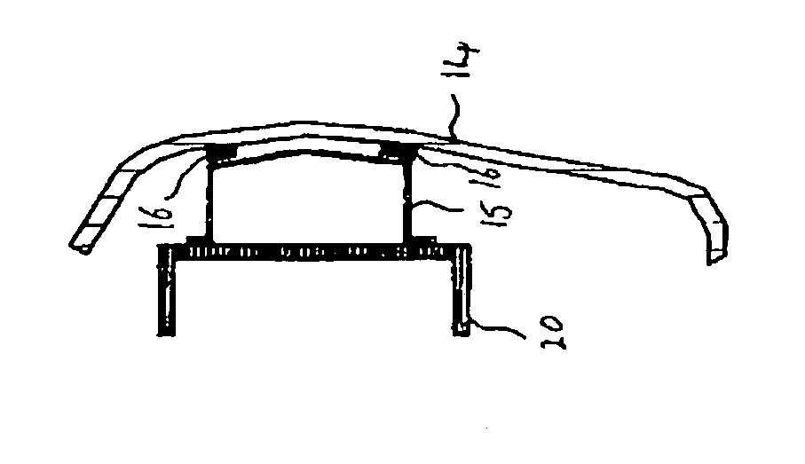
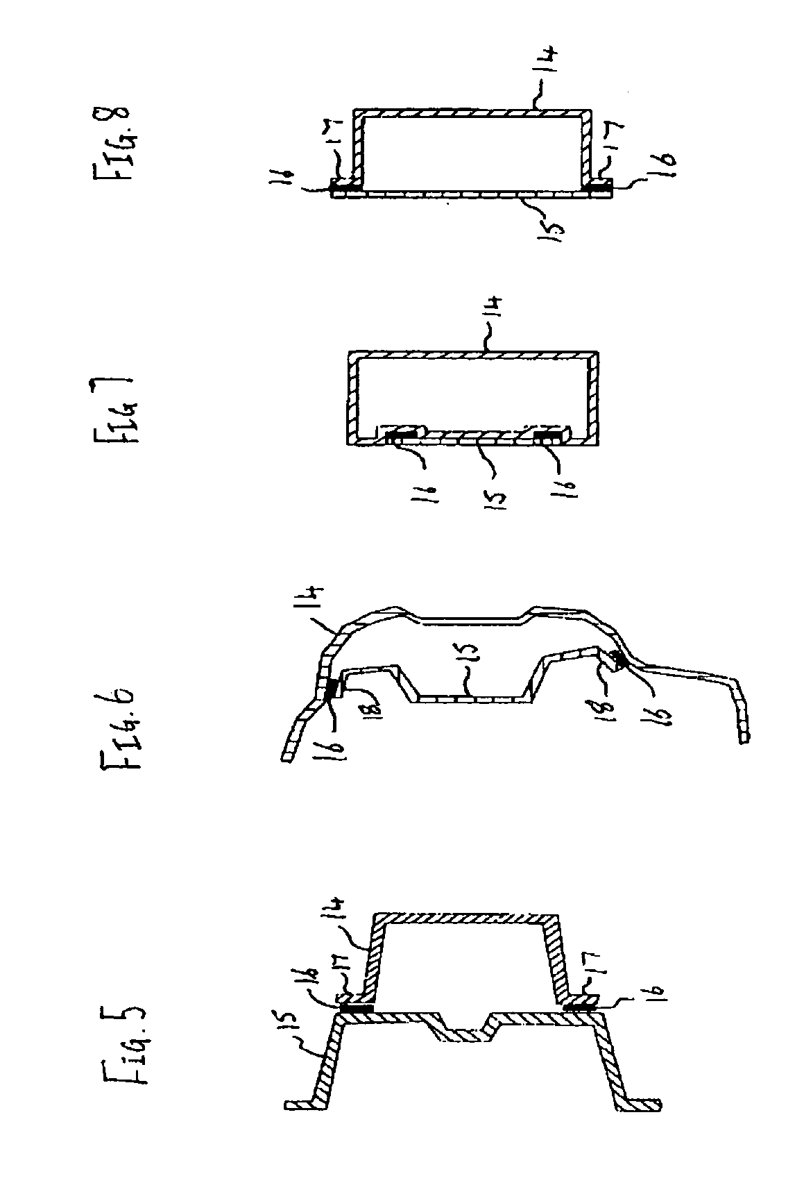
In a preferred embodiment, the structural member and reinforcing member have complementary shapes, at least in part and they are bonded together by application of adhesive on either or both of the complementary parts of the members so as to bond the two parts together over an area which is significantly greater than the area associated with joining the parts by mechanical fixing. Advantageously, bonding the structural member and reinforcing member in this manner reduces the concentration of stress at the joints between the two members. Preferably, the structural member and reinforcing member are bonded together by a continuum of adhesive along the complementary surfaces on the two members in order to reduce the concentration of stress at a particular point when load is applied to the assembly.

The automobile assembly, for example a FEC and a bumper system, is suitably manufactured employing known techniques for producing the structural member for example compression or injection m...


PUM

PropertyMeasurementUnit
surface energyaaaaaaaaaa

Abstract

A method is provided for making an automobile assembly having a moulded plastics structural member and a reinforcing member in which a polymerisable adhesive is employed to bond the two members together and an automobile assembly having a bonded structural member and a reinforcing member. The assembly is suitably used as a “front end carrier” or a bumper system in an automobile.

Description

BACKGROUND TO THE INVENTION This invention relates to an automobile assembly, in particular to structural assemblies employed at the front end known as a “front end carrier” or rear end of an automobile and also to assemblies for use as bumper systems. The invention is especially concerned with automobile structural assemblies having a reinforcing member and a structural member which are connected together by means of an adhesive. An automobile bumper system typically comprises a “bumper beam” and a “bumper fascia”. Typically the bumper beam is bolted to the chassis of the automobile and the fascia is connected to the body panels. An energy absorption unit is typically disposed between the fascia and beam. A bumper beam is typically made of a rigid material, for example steel and aluminium, to provide structural integrity and an impact reaction surface and may act as a reinforcing member in the bumper system. The “bumper fascia” is shaped so as to abut or to be connectable to the ...

Claims


Application Information

Patent Timeline
Patent Type & Authority Applications(United States)
IPC IPC(8): B29C65/48F28D1/00B29L31/30B60R19/04B60R19/18B60R99/00B62D21/15B62D25/08B62D29/00B62D29/04C09J4/00C09J5/00C09J201/00
CPCB62D21/152B62D29/005B62D29/001B62D25/084B62D29/00
Inventor CATE, PETER J.NAUGHTON, PADRAIGKOELMAN, HEIN J.
Owner CATE PETER J
Why Eureka
Try Eureka