Umbrella stand

a technology for umbrellas and stands, applied in the field of umbrellas, can solve the problems of umbrellas to fall, umbrellas to be stowed, and a large amount of ballast required,

Inactive Publication Date: 2005-05-10
ATLEISURE
View PDF7 Cites 66 Cited by
  • Summary
  • Abstract
  • Description
  • Claims
  • Application Information

AI Technical Summary

Benefits of technology

[0010]As will be seen, the present invention overcomes these and other shortcomings associated with prior art umbrella stands. Stated generally, the present invention comprises an improved portable umbrella stand in which the entire device can be shipped in the same shipping carton with the umbrella. Thus there is no need for the umbrella purchaser to make a trip to a store separate from the store from which the umbrella is purchased in order to obtain suitable ballast. Further, the umbrella owner does not have to lug ballast to the location where the umbrella will be used.

Problems solved by technology

If the umbrella is of a tilting design, then whenever the umbrella canopy is tilted such that its center of gravity is no longer directly above the umbrella mount, considerable torque is be exerted on the mount and may tend to cause the umbrella to topple over.
The requirement for ballast presents a number of problems.
Costs of shipping packages of heavy weight make it economically impractical to include the ballast along with the umbrella.
In addition, commonly used forms of ballast such as concrete blocks and the like will not fit within the typical umbrella box, which is only about ten inches wide by six inches deep.
Further, many stores which sell patio umbrellas do not sell concrete blocks or other suitable objects for use as ballast, meaning the purchaser must travel to another store after purchasing the umbrella to obtain the ballast.
In addition, there is the problem of the umbrella owner having to haul heavy concrete blocks to the location where the umbrella will be used.

Method used


Image

  • Umbrella stand
  • Umbrella stand
  • Umbrella stand

Examples


Embodiment Construction

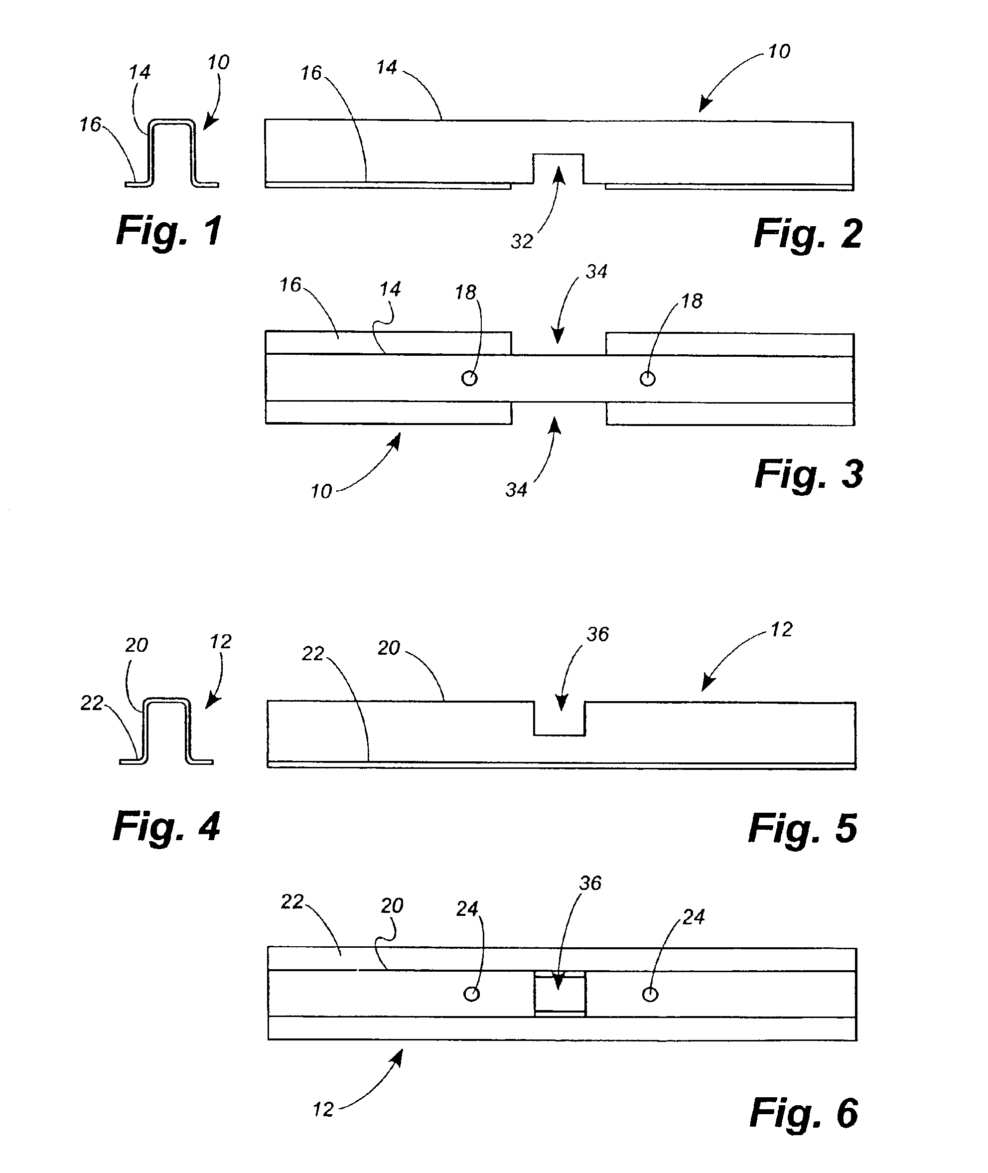
[0036]Referring now to the drawings, in which like numerals indicate like elements throughout the several views, FIGS. 1-3 depict an upper cross base member 10, and FIGS. 4-6 depict a lower cross base member 12. As will be described below, the upper and lower cross base members 10, 12 assemble to form a cross base.

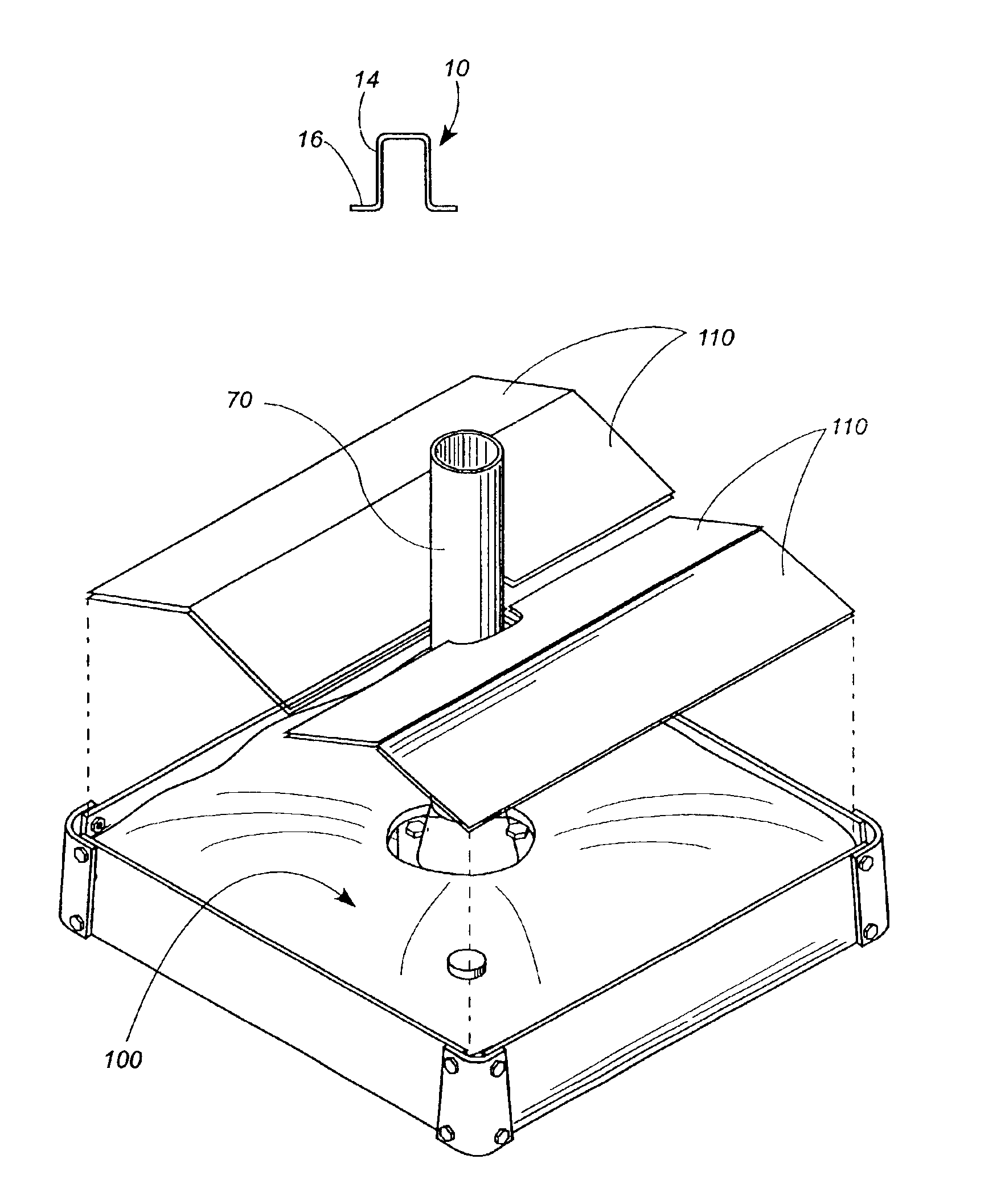
[0037]Referring to FIGS. 1-3, the upper cross base member 10 comprises a channel member 14 in the shape of an inverted “U.” Flanges 16 project laterally outward from the lower ends of the channel member 14. A pair of threaded bores 18 are formed in the upper surface of the channel member 14.

[0038]Similarly, as shown in FIGS. 4-6, the lower cross base member 12 comprises a channel member 20 in the shape of an inverted “U.” Flanges 22 project laterally outward from the lower ends of the channel member 20, and a pair of threaded bores 24 are formed in the upper surface of the channel member 20.

[0039]Referring again to FIG. 2, the upper cross base member 10 has a generally rec...


PUM


Abstract

An umbrella stand includes means defining a cavity, a mast receiving means operatively associated with the cavity-defining means, a bladder received within the cavity and comprised of a material which will retain ballast, and ballast contained within the bladder. When an umbrella mast is inserted into the mast receiving means and the umbrella is raised, the ballast weighs down the cavity-defining means so as to maintain the umbrella in a generally upright condition.

Description

TECHNICAL FIELD[0001]The present invention relates generally to umbrellas and relates more specifically to an umbrella stand for maintaining an umbrella in an upright position.BACKGROUND OF THE INVENTION[0002]Patio umbrellas are well known in which an umbrella canopy is mounted to a mast to provide shade for a deck, patio, garden, or the like. If the umbrella is of a tilting design, then whenever the umbrella canopy is tilted such that its center of gravity is no longer directly above the umbrella mount, considerable torque is be exerted on the mount and may tend to cause the umbrella to topple over. Even win the umbrella canopy is not tilted, breezes can exert forces on the umbrella which tend to topple it. And in the case of side mast umbrellas, where the umbrella canopy is cantilevered out to the side of the mast, the torque exerted on the umbrella base by the dead weight of the umbrella canopy can be much higher, and even higher still on breezy days.[0003]In applications where t...

Claims


Application Information

Patent Timeline
Patent Type & Authority Patents(United States)
IPC IPC(8): E04H12/22A45B23/00
CPCE04H12/2246A45B23/00Y10S248/91A45B2023/0012
Inventor HARBAUGH, KENNETH A.
Owner ATLEISURE
Why Eureka
Try Eureka