
Actuating device for emergency operation of a gearless drive machine of an elevator

Inactive Publication Date: 2005-05-10
INVENTIO AG
View PDF8 Cites 7 Cited by
  • Summary
  • Abstract
  • Description
  • Claims
  • Application Information

AI Technical Summary

Benefits of technology

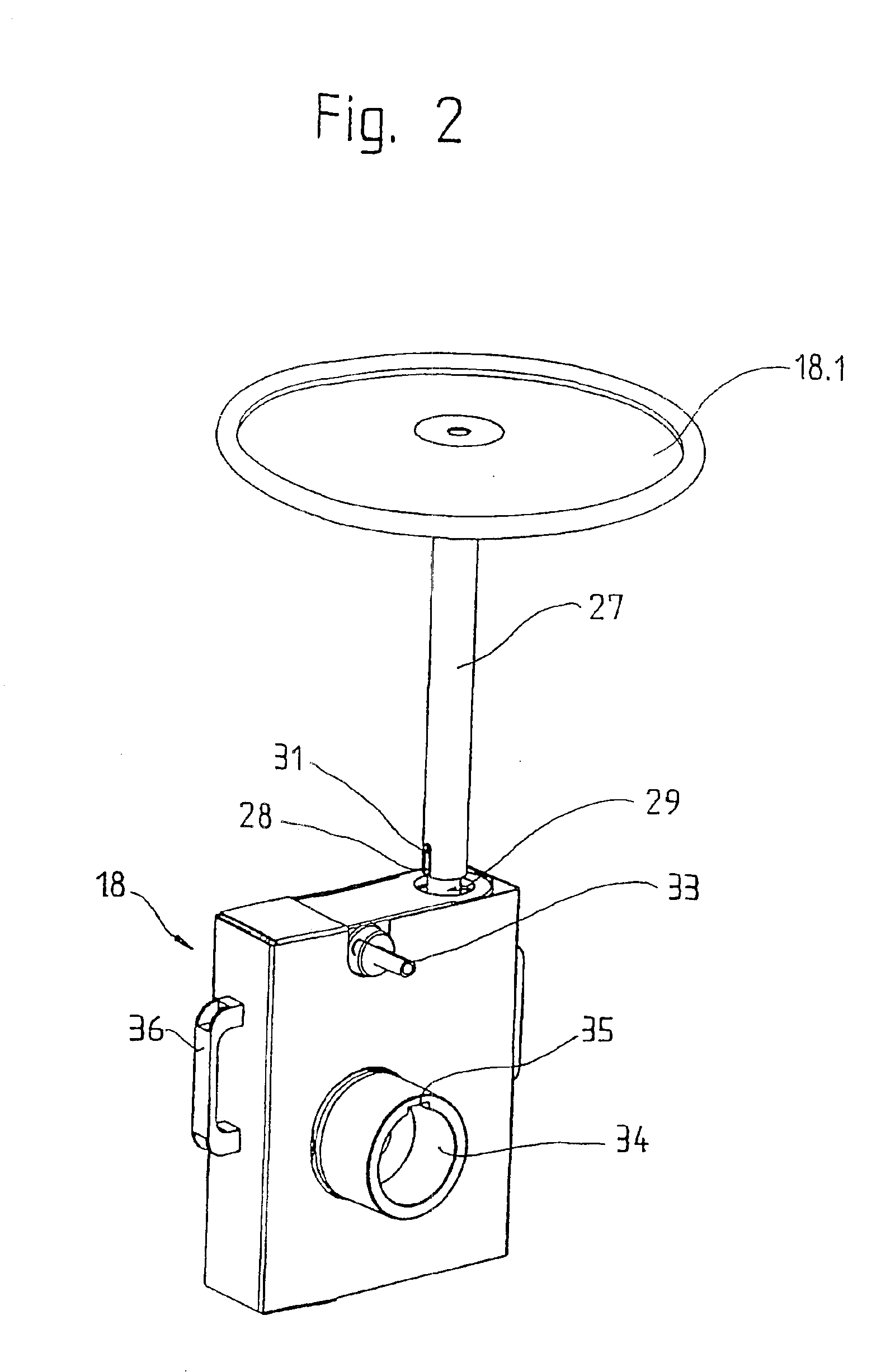
[0008]The invention comprises a gearless drive machine having a motor with a shaft that supports a traction sheave for elevator car and counterweight support ropes pass and braking device for the motor arranged on a bearing pedestal. An actuating device for emergency activation of the braking device comprises a hand drive unit which can be manually engaged with the motor shaft and has a handwheel which, when the hand drive unit is engaged with the motor shaft, allows the motor shaft to be manually turned. An interlock may be provided to insure that electrical power is not provided to the motor when the drive unit is engaged. The invention provides a solution to avoiding the disadvantages of the known device and creating a handwheel by means of which emergency operation of the elevator is trouble-free and safe.
[0009]The advantages achieved by the invention are essentially to be seen in that the hand drive can be mounted easily and without tools. When needed, the hand drive can be mounted on the drive machine. A coupling such as required with a permanently installed hand drive is no longer necessary. The safety of the persons performing the emergency operation is assured in all cases, since the electric drive is switched off automatically when the hand drive is mounted. Furthermore, in the case of an elevator installation with several elevators, it is sufficient for there to be one hand drive which can be used on whichever elevator requires emergency operation.

Problems solved by technology

A disadvantage of the known device is that the handwheel is situated close to the motor.
When the handwheel is turned, fingers can easily be caught and trapped by the rotating handwheel.
Releasing the brake is made difficult by the brake being situated at one end of the motor and the handwheel at the other end.
Such equipment is expensive, awkward, and not without danger in operation.

Method used


Image

  • Actuating device for emergency operation of a gearless drive machine of an elevator
  • Actuating device for emergency operation of a gearless drive machine of an elevator
  • Actuating device for emergency operation of a gearless drive machine of an elevator

Examples


Embodiment Construction

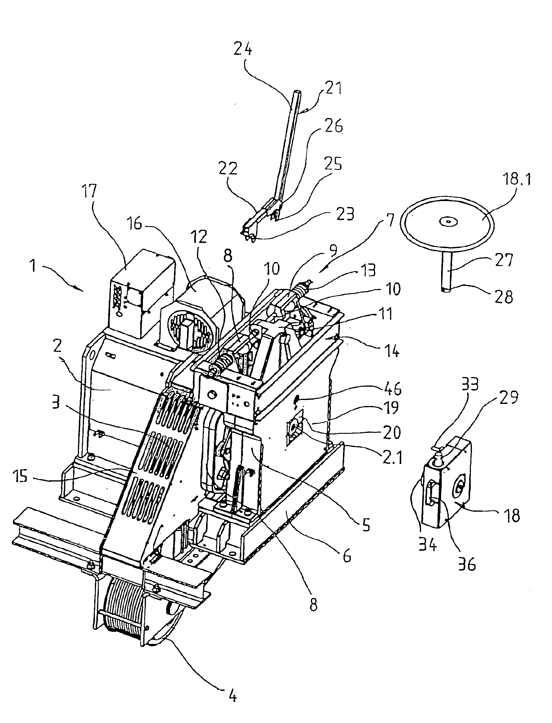
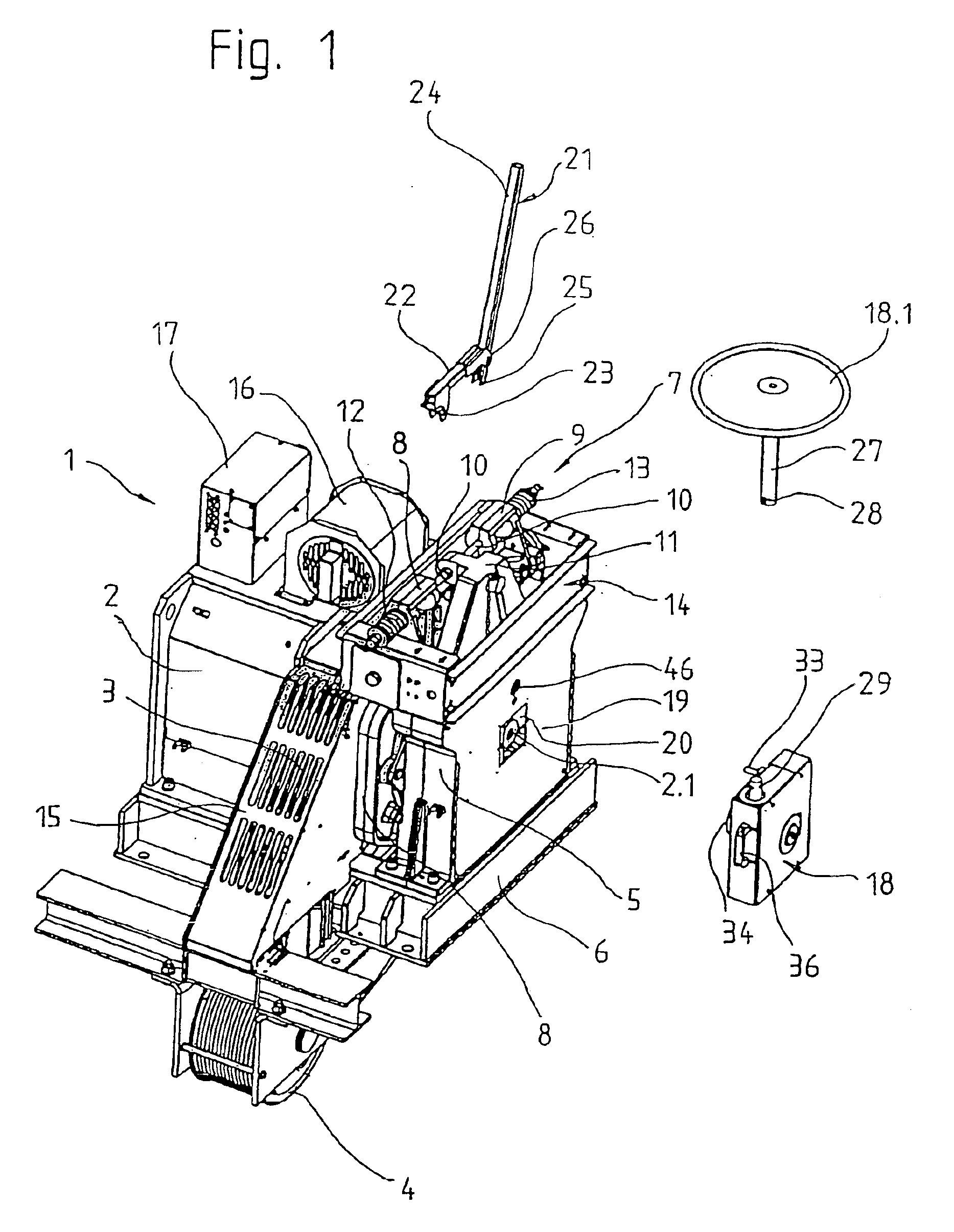
[0015]FIG. 1 shows a gearless drive machine 1 with a motor 2, comprising a stator and a rotor, which drives a traction sheave 3. Passing over the traction sheave 3 and a deflector sheave 4 are ropes (not shown) which support and drive an elevator car (not shown) and a counterweight (not shown). The traction sheave 3 is borne by a motor shaft 2.1 which is held in bearings located at one end in a bearing endplate (not shown) and located at the other end in a bearing pedestal 5. Motor 2, the endplate, bearing pedestal 5, and deflector sheave 4 are borne by a machine bracket 6.

[0016]The drive machine includes a braking device 7 with a first brake arm 8 and a second brake arm 9, on each of which arms a brake shoe is arranged. At their lower ends, the brake arms 8, 9 are pivoted on the bearing pedestal 5, and at their upper ends are guided by a rod 10. The rod 10 is arranged with its mid-point in a support 11 which is connected to the bearing pedestal 5. To actuate the brake shoes, each b...


PUM


Abstract

An actuating device for an elevator having a gearless drive having a motor, a traction sheave over which support ropes are passed and a motor braking device is in the form of a hand drive adapted to be engaged with the motor shaft for emergency elevator operation with a handwheel for manual motor shaft activation. The hard drive may include a gear coupling the handwheel and an output coupling in the form of a grooved hub. The braking device of the elevator is mounted to a pedistal having a cover with an opening through which the hub may be inserted to engage the motor shaft.

Description

[0001]The present invention is a continuation of PCT / CH01 / 00301, filed May 16, 2001.[0002]The invention relates to a gearless drive machine of an elevator, comprising a motor, a traction sheave which is borne on a motor shaft and over which the ropes for supporting and moving an elevator car and a counterweight are passed, a braking device which is arranged on a bearing pedestal and serves to bring the motor to a standstill, and an actuating device for emergency operation by means of which the motor can be manually actuated.BACKGROUND OF THE INVENTION[0003]From patent specification EP 0 706 968 A2 a drive unit for an elevator has become known. The drive unit has passing through it a shaft which serves both as the shaft for a motor and a shaft for a gear. Arranged at one end of the shaft is a gear with a traction sheave for the elevator rope. Attached to the free, motor end of the shaft is a handwheel for emergency operation of the drive unit.[0004]Fastened by pivoted joints to a bas...

Claims


Application Information

Patent Timeline
IPC IPC(8): B66B5/02
CPCB66B5/027
Inventor CHOLINSKI, ANDRZEJ
Owner INVENTIO AG
Learn More