Bumper core
a bumper and core technology, applied in the direction of bumpers, shock absorbers, elastic dampers, etc., can solve the problems of complex structure, unrecoverable fracture with permanent damage, and no bumper cores on the market satisfy the above requirements, so as to achieve considerable improvement in the protection of pedestrians
- Summary
- Abstract
- Description
- Claims
- Application Information
AI Technical Summary
Benefits of technology
Problems solved by technology
Method used
Image
Examples
example 1
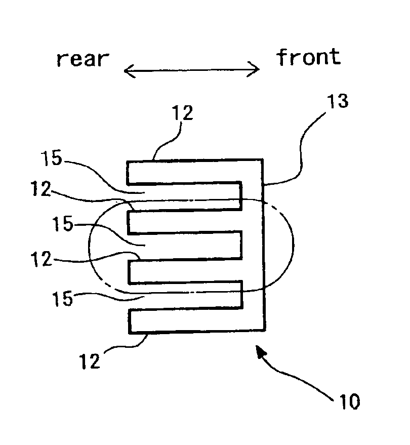
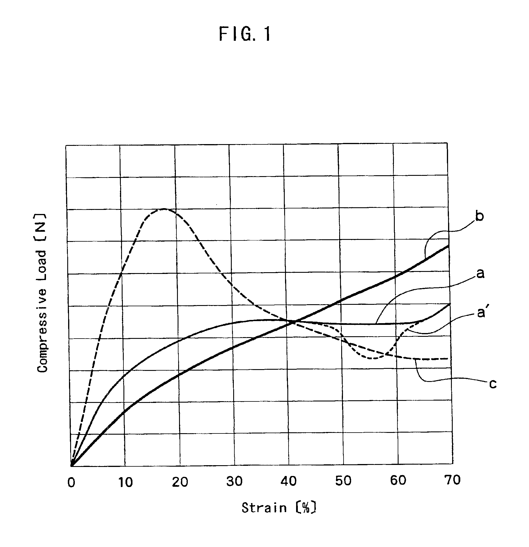
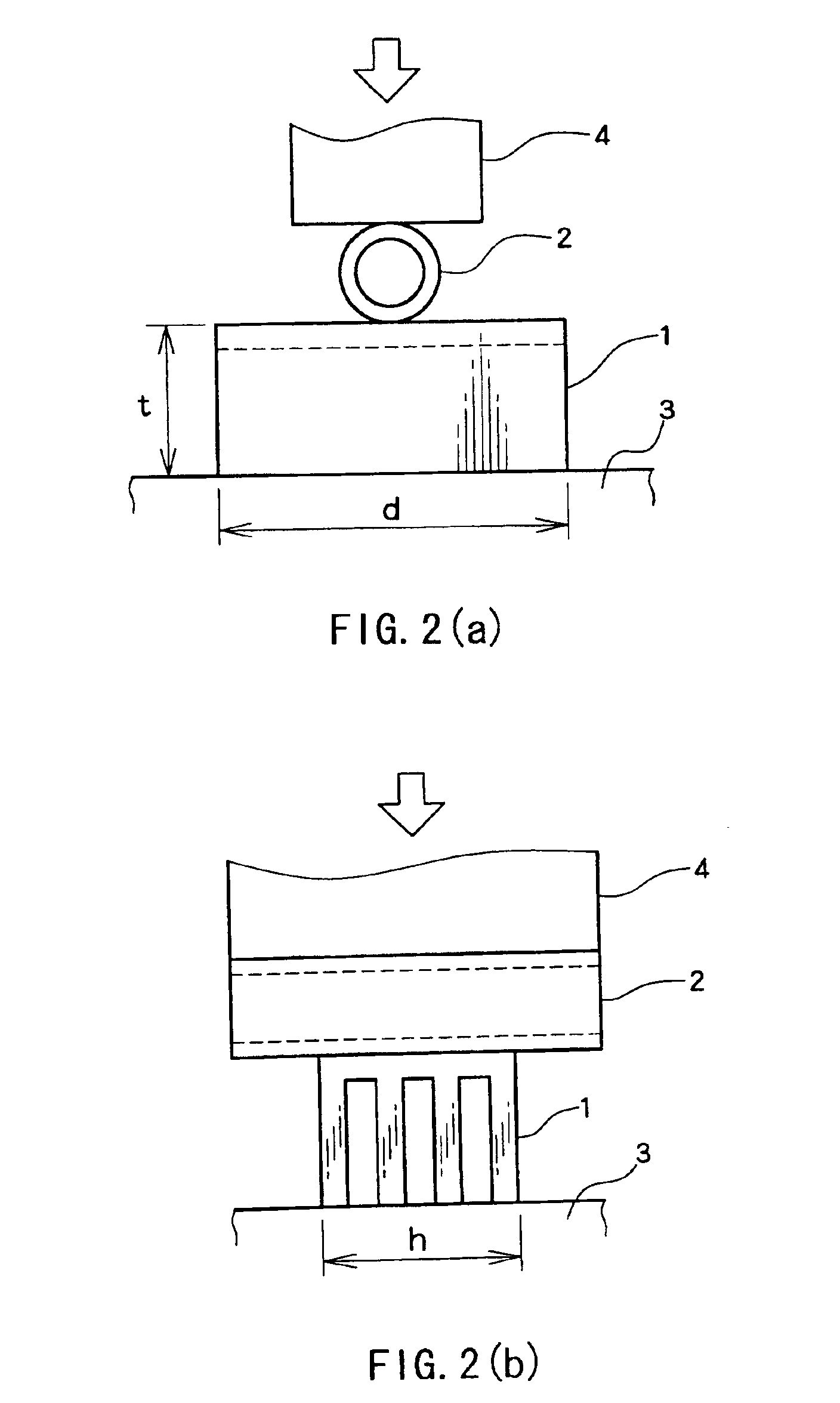
[0076]Expanded beads (apparent density D1: 0.14 g / cm3) of a propylene homopolymer resin having a tensile modulus of 1,440 MPa were filled in a mold and heated with steam to obtain a foamed molding in the form of a bumper core having a maximum length L in the front-to-rear direction of 38 mm. The core was composed of a front wall, and two, parallel plate-like legs extended rearwardly from the front wall and also lengthwise of the core. From the essential portion of the thus obtained core were cut out specimens as shown in FIG. 9(a) each having a length “d” of 170 mm in the lengthwise direction of the core, the length “t” of 38 mm in the front-to-rear direction of the core and a vertical length “h” of 100 mm along the vertical direction of the core. Each specimen had two legs with a length H in the front-to-rear direction of 32 mm and a thickness T in the vertical direction of 8 mm. The specimens were measured for a compressive load F20 at 20% strain, a compressive load F40 at 40% str...
example 2
[0078]Using the same expanded beads as used in Example 1, a bumper core was molded in the same manner as in Example 1 having a maximum length L in the front-to-rear direction of 38 mm. The core was composed of a front wall, and four, parallel, equally spaced apart plate-like legs extending rearwardly from the front wall and also lengthwise of the core. From the essential portion of the thus obtained core were cut out specimens as shown in FIG. 9(b) each having a length “d” of 170 mm in the lengthwise direction of the core, the length “t” of 38 mm in the front-to-rear direction of the core and a vertical length “h” of 100 mm along the vertical direction of the core. Each specimen had four legs with a length H in the front-to-rear direction of 32 mm and a thickness T in the vertical direction of 8 mm. The F20, F40, F60, F20 / F40, F60 / F40, VT / (VT+VV) and D2 of the core and bending loads BL and BF of the leg are shown in Tables 1 and 2.
example 3
[0079]Using the same expanded beads as used in Example 1, a bumper core was molded in the same manner as in Example 1 having a maximum length L in the front-to-rear direction of 38 mm. The core was composed of a front wall, and five, parallel, equally spaced apart plate-like legs extending rearwardly from the front wall and also lengthwise of the core. From the essential portion of the thus obtained core were cut out specimens as shown in FIG. 9(c) each having a length “d” of 170 mm in the lengthwise direction of the core, the length “t” of 38 mm in the front-to-rear direction of the core and a vertical length “h” of 100 mm along the vertical direction of the core. Each specimen had five legs with a length H in the front-to-rear direction of 32 mm and a thickness T in the vertical direction of 8 mm. The F20, F40, F60, F20 / F40, F60 / F40, VT / (VT+VV) and D2 of the core and bending loads BL and BF of the leg are shown in Tables 1 and 2.
PUM
 Abstract
Description
Claims
Application Information
 - R&D
- Intellectual Property
- Life Sciences
- Materials
- Tech Scout
- Unparalleled Data Quality
- Higher Quality Content
- 60% Fewer Hallucinations
Browse by: Latest US Patents, China's latest patents, Technical Efficacy Thesaurus, Application Domain, Technology Topic, Popular Technical Reports.
© 2025 PatSnap. All rights reserved.Legal|Privacy policy|Modern Slavery Act Transparency Statement|Sitemap|About US| Contact US: help@patsnap.com


