Front structure of a motor vehicle

a front structure and motor vehicle technology, applied in the direction of vehicle body, superstructure subunit, monocoque construction, etc., can solve the problem that conventional bumpers usually cannot perform such a carrier function, and achieve the effect of improving pedestrian protection and high section modulus

Active Publication Date: 2010-06-15
DR ING H C F PORSCHE AG
View PDF7 Cites 8 Cited by
  • Summary
  • Abstract
  • Description
  • Claims
  • Application Information

AI Technical Summary

Benefits of technology

[0007]The invention relates to a front structure of a motor vehicle having upper and lower bumpers that extend in the transverse direction of the vehicle. Both bumpers are supported on the body of the motor vehicle, such as on the body or the body frame, by crash boxes, and preferably in each case by two crash boxes. In this context, “crash box” is a term of art in the bumper technology and refers to a generally polygonal or rounded tubular structure having a rear end with flanges that connect to the vehicle and a front end connected to the bumper. The lower bumper has a closed hollow profile. In this context, a closed hollow profile can be a tube formed by extrusion or other known tube forming techniques. The closed hollow profile also can be formed by two opposed channels welded or otherwise secured with their concave surfaces facing one another. Still further, the closed hollow profile can be formed by securing a plate to the concave side of a U-shaped channel. The closed hollow channel can be of uniform or non-uniform cross-section along its length from side-to-side on the motor vehicle. The cross-sectional shape at specific locations may be selected in accordance with other structures that may be connected to the lower bumper, as explained herein. Opposite ends of the lower bumper may be open or closed. The closed hollow profile of the lower bumper results in a considerably higher section modulus than an open hollow profile. The higher section modulus makes it possible to fasten further components, such as trim panel parts, to the lower bumper. Additionally, the hollow profile of the lower bumper provides improved pedestrian protection. At least the lower bumper may be supported on a luggage compartment depression of the motor vehicle.
[0009]An energy absorbing impact element, such as a foam, preferably is clipped at least to the upper bumper. The clip connection enables the impact element to be fastened to the upper bumper quickly by hand and in an extremely simple manner. Thus, it is possible to avoid a complex and expensive assembly step during the production of the motor vehicle.
[0010]The lower bumper preferably is embodied as the carrier of a trim panel. Additionally, the closed hollow profile of the lower bumper provides a higher section modulus, and hence enables the lower bumper to be used simultaneously as a carrier for further components. Such components in a front region of a motor vehicle may, for example, be a trim panel, a front apron and / or a spoiler. Conventional bumpers usually cannot perform such a carrier function, because conventional bumpers often do not have the stiffness required to be a carrier element. A further energy-absorbing impact element may be arranged between the lower bumper and the trim panel, and as a result the consequential injuries in the event of a pedestrian impact can be reduced further. The further impact element can be fastened to the lower bumper in a fashion similar to that used on the upper bumper, for example by means of clips.

Problems solved by technology

Conventional bumpers usually cannot perform such a carrier function, because conventional bumpers often do not have the stiffness required to be a carrier element.

Method used


Image

  • Front structure of a motor vehicle
  • Front structure of a motor vehicle

Examples


Embodiment Construction

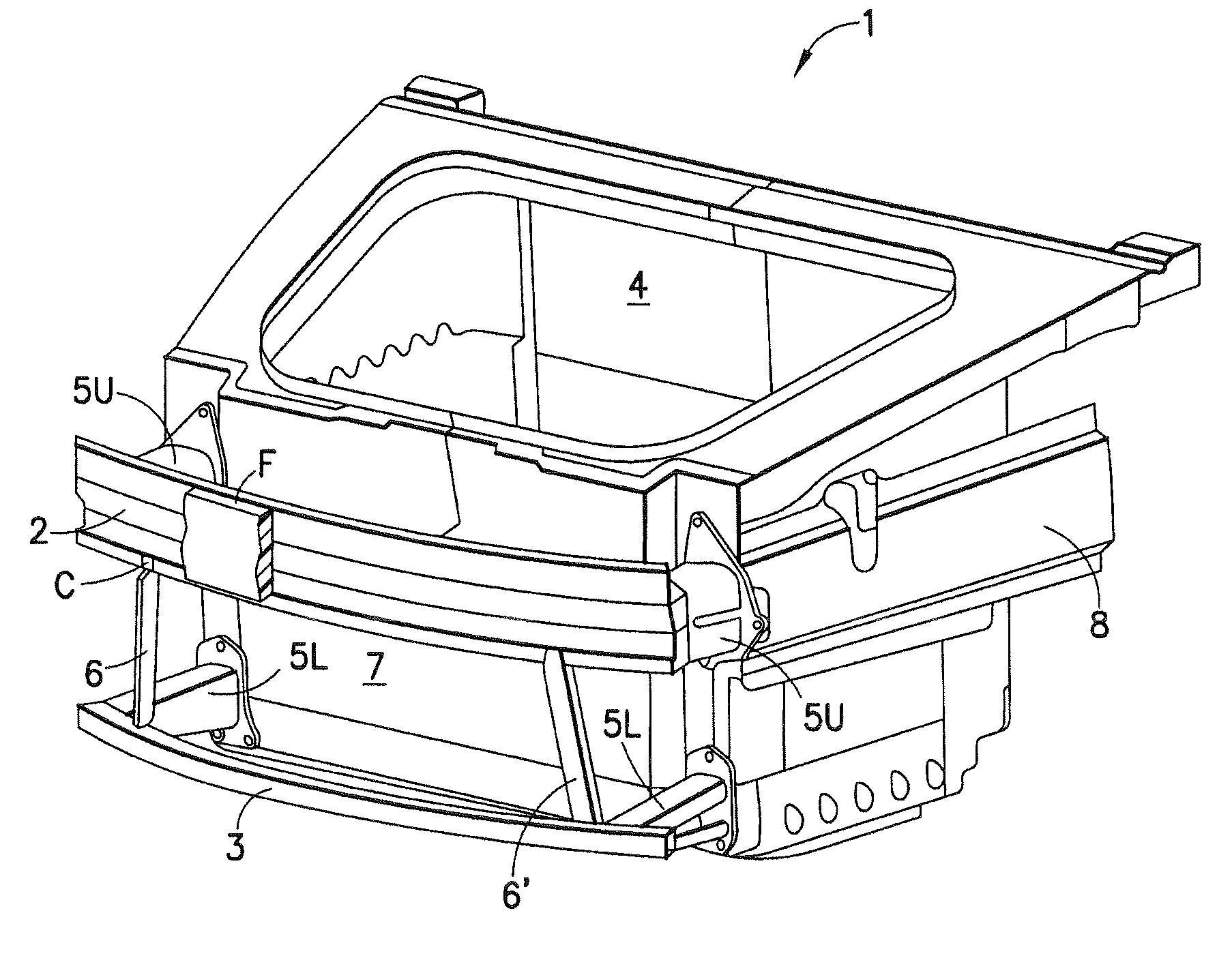
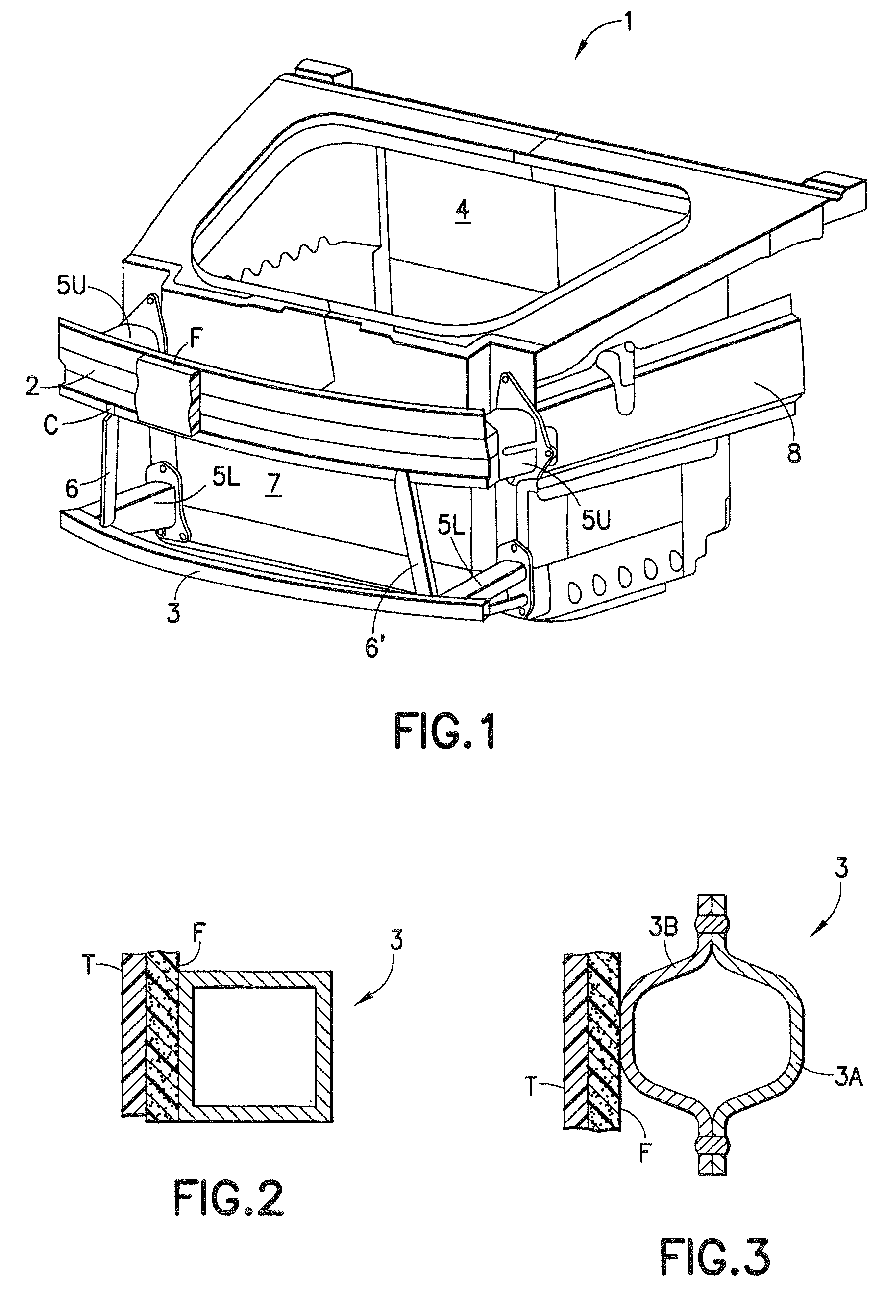
[0015]The front structure of a motor vehicle according to the invention is identified by the numeral 1 in FIG. 1. The front structure 1 has an upper bumper 2 and a lower bumper 3 that run in the vehicle transverse direction at a position in front of a luggage compartment depression 4 of the motor vehicle as viewed in the direction of travel. Opposite lateral ends of the upper bumper 2 are connected to a front-end body by two upper crash boxes 5U and opposite lateral ends of the lower bumper 3 are connected to the front-end body by two lower crash boxes 5L. The crash boxes 5L and 5U enable an energy-absorbing deformation in the event of an impact of the motor vehicle against an obstacle or in the event of an impact of a pedestrian against the motor vehicle. The lower bumper 3 defines a closed hollow profile. Thus, the lower bumper 3 may define a hollow extruded tube, of preferably polygonal cross-section as shown in FIG. 2. Alternatively, the lower bumper 3 may be formed from two U-s...


PUM


Abstract

A front structure of a motor vehicle has a lower bumper that runs in the vehicle transverse direction, and an upper bumper arranged above the lower bumper. The lower bumper and upper bumper are supported on the vehicle structure via crash boxes. The lower bumper defines a closed hollow profile and is supported on a front-end body, in particular on a luggage compartment depression, of the motor vehicle via the associated crash boxes.

Description

[0001]This application claims priority under 35 USC 119 to German Patent Application No. 10 2008 039 972.8 filed on Aug. 27, 2008, the entire disclosure of which is incorporated herein by reference.BACKGROUND OF THE INVENTION[0002]1. Field of the Invention[0003]The invention relates to a front structure of a motor vehicle having a lower bumper that runs in the transverse direction of the vehicle and an upper bumper arranged above the lower bumper.[0004]2. Description of the Related Art[0005]EP 1 451 041 B1 discloses a generic front structure of a motor vehicle in which a foam layer with a front surface is provided on the front side of an upper bumper to limit the forces that act on the legs of a pedestrian in the event of a collision with the pedestrian. A lower bumper is at approximately the same level as or in front of the front surface of the upper bumper, and lateral ends of the two bumpers are fastened to longitudinal beams of the motor vehicle. Energy-absorbing crash boxes are...

Claims


Application Information

Patent Timeline
Patent Type & Authority Patents(United States)
IPC IPC(8): B60R19/26
CPCB62D25/082
Inventor WURTEMBERGER, RALF
Owner DR ING H C F PORSCHE AG
Why Eureka
Try Eureka