Catheter shaft junction having a polymeric reinforcing member with a high glass transition temperature

a polymer reinforcement member and glass transition technology, applied in the field of catheters, can solve the problems of forming flexible junctions, kink resistance and ruggedness, prior art designs have suffered from various drawbacks, etc., and achieves the effects of low profile, suitable stiffness transition, and excellent dimension stability

Inactive Publication Date: 2006-05-02
ABBOTT CARDIOVASCULAR
View PDF25 Cites 91 Cited by
  • Summary
  • Abstract
  • Description
  • Claims
  • Application Information

AI Technical Summary

Benefits of technology

[0006]The invention is generally directed to a catheter, and preferably a balloon catheter, having a polymeric reinforcing member at a junction between shaft sections such as the junction between the proximal shaft section and the distal shaft section. In a presently preferred embodiment, the balloon catheter is a rapid exchange type catheter. The polymeric reinforcing member is around or within either or both of the tubular member defining the inflation lumen or the tubular member defining the guidewire lumen at the rapid exchange junction. The reinforcing tubular member at the rapid exchange junction of the shaft prevents or inhibits damage to the tubular members defining the inflation lumen and / or guidewire lumen during assembly or use of the catheter, and thus avoids a loss of lumen integrity.
[0008]The polymeric reinforcing member is preferably a tube having a shape configured to correspond to the shape of the proximal portion of the inner tubular member or the distal portion of the proximal tubular member, such as a circular, oblong / oval, D-shaped or C-shaped transverse cross section. However, a variety of suitable shapes may be used depending on the shape of the inner tubular member and the proximal tubular member. In a presently preferred embodiment, the polymeric reinforcing member is formed of a first polymeric material having a glass transition temperature greater than a glass transition temperature of a second polymeric material forming the distal portion of the proximal tubular member or the proximal portion of the inner tubular member. The first polymeric material forming the polymeric reinforcing member is preferably a high temperature, high modulus material, having a glass transition temperature (Tg) of about 300° C. to about 450° C., and a tensile modulus, expressed as a secant modulus (ASTM D882) of about 350,000 to about 450,000 psi. In one embodiment, the first polymeric material forming the polymeric reinforcing member is selected from the group consisting of thermoset polyimide and thermoplastic polyimide. The thermoset or thermoplastic polyimide has a high secant modulus of greater than about 350,000 psi, with about 25,000 to about 30,000 psi tensile strength, which allows for a thin-walled reinforcing tube which nonetheless has a sufficient strength to provide the required reinforcement. In a presently preferred embodiment, thermoset polyimide is used, due to the high glass transition temperature of the thermoset polyimide. The thermoset polyimide has a very high glass transition temperature (Tg) of approximately 400° C. (as measured by differential scanning calorimetry (DSC)), and thus excellent dimensional stability at the processing temperature of other polymers such as polyamides and polyurethanes commonly used in catheter components. As a result, the polyimide tube maintains thin-walled, controlled dimensions during formation and assembly of the catheter, and specifically during high temperature fusion (i.e., thermal) bonding of the tubular members to form the rapid exchange junction. Thermoplastic polyimide, which has a Tg of about 250° C., may also be used, but is less preferred than the high glass transition temperature thermoset polyimide.
[0010]The polymeric reinforcing member has sufficient wall thickness to prevent or inhibit the formation of a break in the wall of the tubular members defining the inflation lumen and the guidewire lumen at the rapid exchange junction. During assembly of the catheter, assembly mandrels or rods (hereafter “assembly rods”), are placed in the lumens of the proximal tubular member and the distal inner tubular member, to keep the lumens open during fusion of the tubular members to form the rapid exchange junction. Heat, and pressure from shrink tubing are applied to the tubular members to fusion bond the tubular members together and form the rapid exchange junction at the transition between the proximal or an intermediate shaft section and the distal shaft section at the guidewire proximal port. The polymeric reinforcing member prevents or inhibits loss of integrity of the inner tubular member and proximal tubular member caused by junction formation as the heated polymeric material of the tubular members are flow together during fusion bonding. Thus, leaks in the guidewire and inflation lumens are prevented or inhibited by the polymeric reinforcing member with a high glass transition temperature.
[0013]The catheter of the invention maintains the integrity of the inflation lumen and guidewire lumen throughout assembly and use of the catheter, due to the polymeric reinforcing member. The thin-walled polymeric reinforcing member has excellent dimension stability providing a rapid exchange junction having a low profile and a suitable stiffness transition between proximal and distal portions of the catheter, to thereby improve handling and performance and minimize kinking. These and other advantages of the invention will become more apparent from the following detailed description and exemplary drawings.

Problems solved by technology

One difficulty has been forming a junction which is flexible, yet kink resistant and rugged.
Despite these attempts, prior art designs have suffered from various drawbacks relating to these handling and performance issues.

Method used


Image

  • Catheter shaft junction having a polymeric reinforcing member with a high glass transition temperature
  • Catheter shaft junction having a polymeric reinforcing member with a high glass transition temperature
  • Catheter shaft junction having a polymeric reinforcing member with a high glass transition temperature

Examples


Embodiment Construction

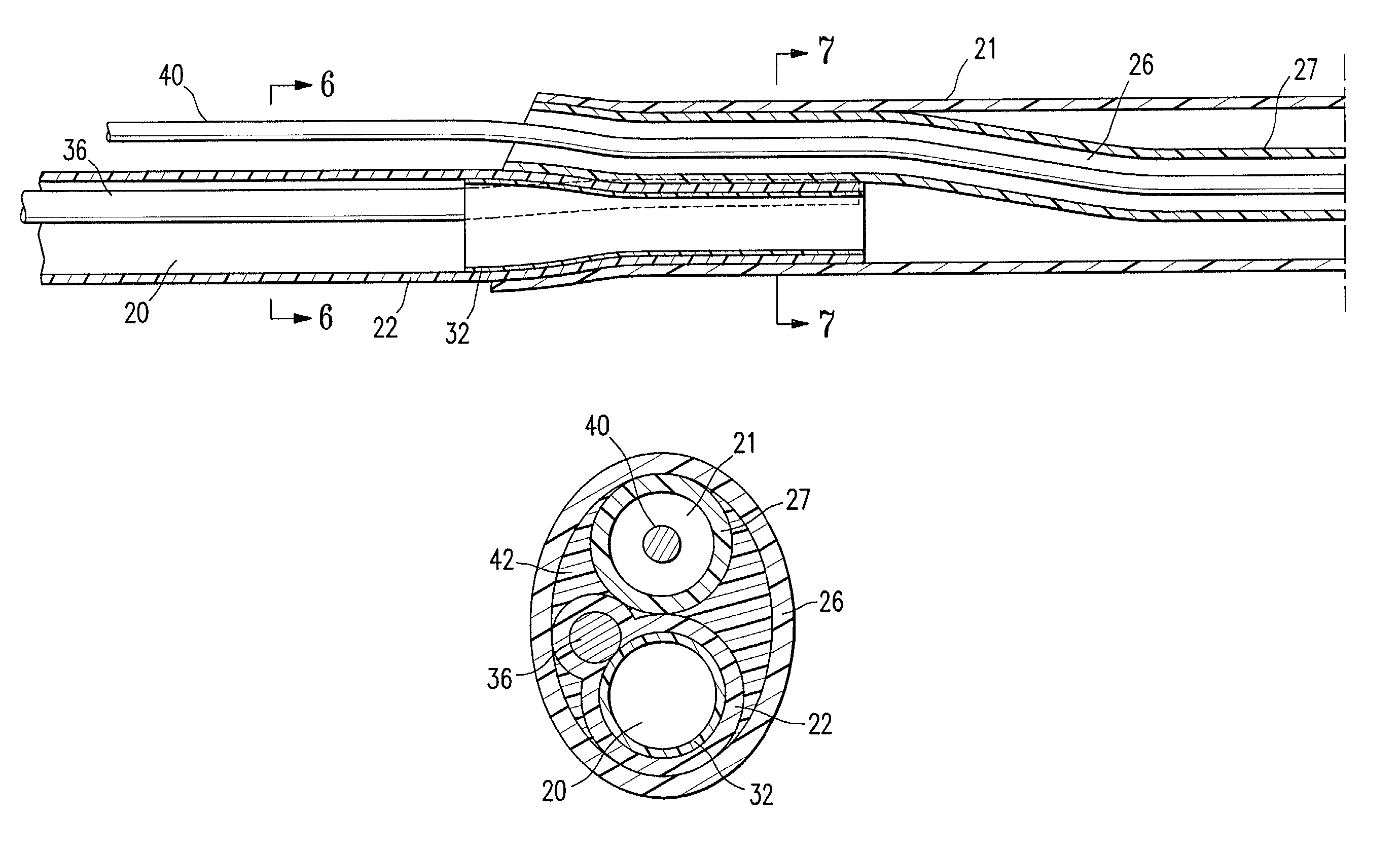
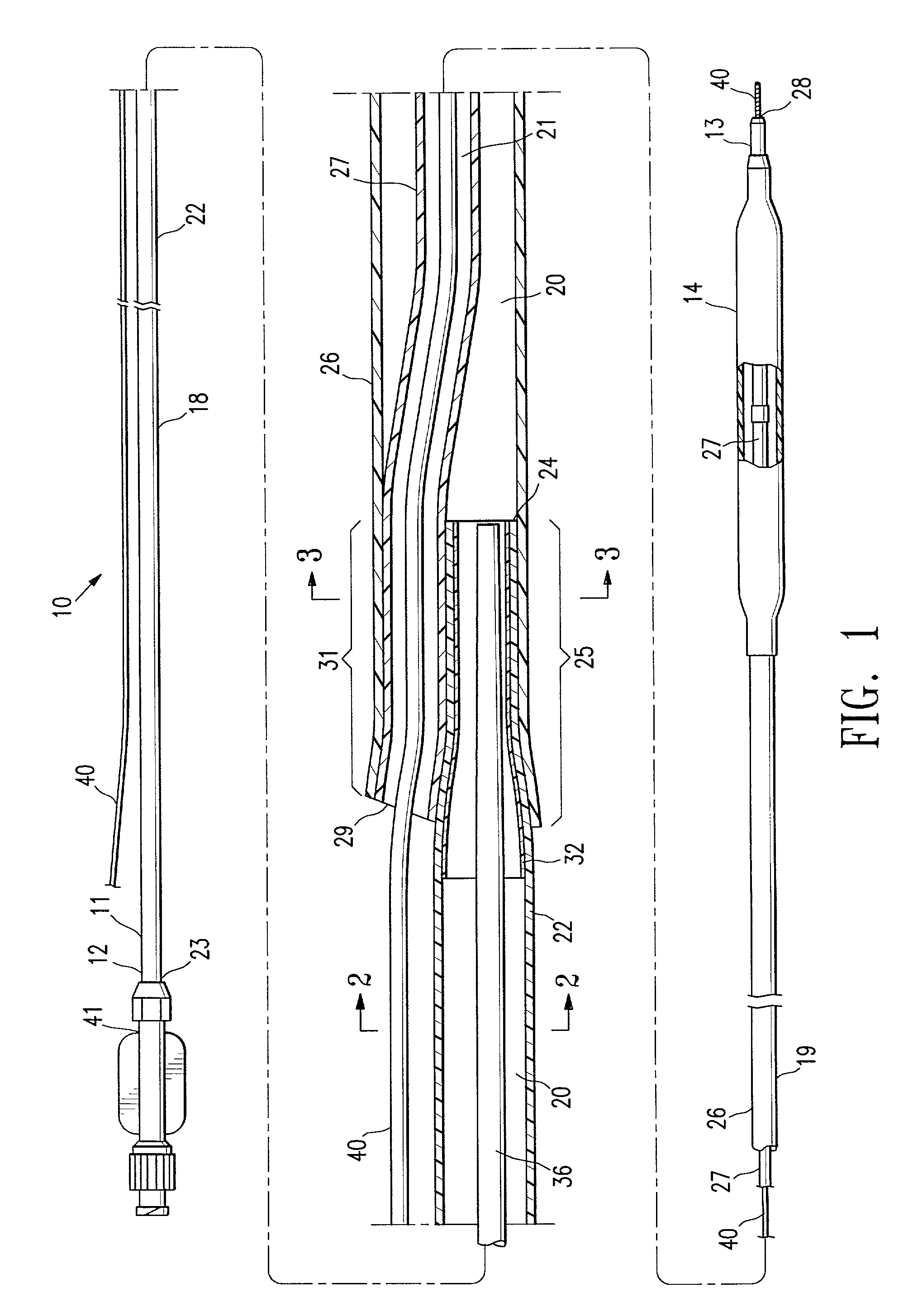
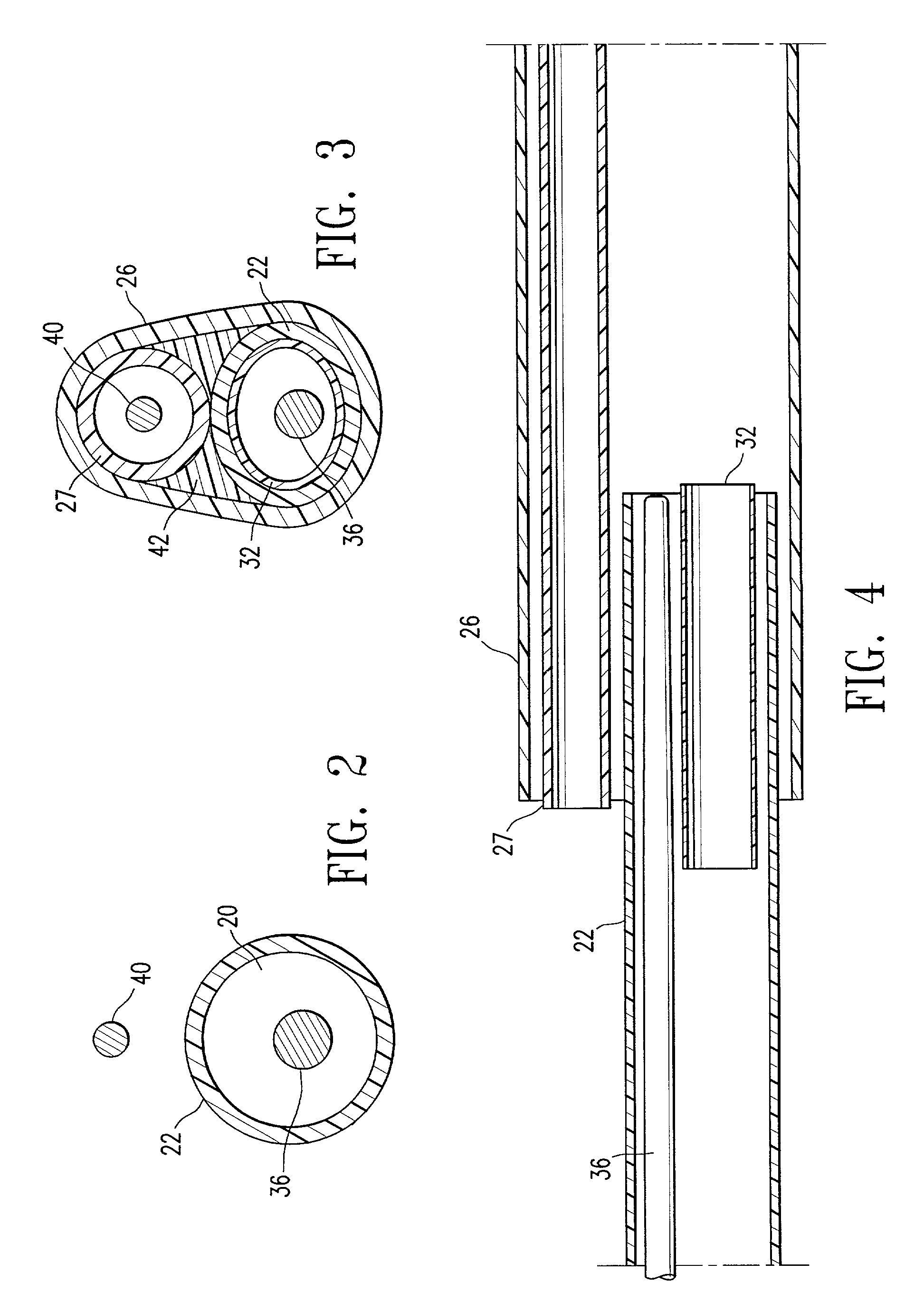
[0027]FIG. 1 illustrates rapid exchange type balloon catheter 10 embodying features of the invention. Catheter 10 generally comprises an elongated catheter shaft 11 having a proximal end 12, a distal end 13, a proximal shaft section 18 and a distal shaft section 19 at the distal end of the proximal shaft section, and an inflatable balloon 14 on the distal shaft section. The shaft 11 has an inflation lumen 20, and a guidewire receiving lumen 21. The proximal shaft section 18 comprises a proximal tubular member 22 defining a proximal portion of the inflation lumen 20, and having a proximal end 23, a distal end 24, and a distal portion 25. In the embodiment illustrated in FIG. 1, the distal end of the proximal tubular member 22 tapers distally to a smaller transverse dimension. The distal shaft section 19 comprises an outer tubular member 26 defining a distal portion of the inflation lumen 20, and an inner tubular member 27 defining the guidewire lumen 21 in fluid communication with a ...


PUM

PropertyMeasurementUnit
glass transition temperatureaaaaaaaaaa
lengthaaaaaaaaaa
wall thicknessaaaaaaaaaa

Abstract

A catheter having a polymeric reinforcing member at a junction between shaft sections such as a rapid exchange catheter junction. The polymeric reinforcing member is around or within the tubular member defining the inflation lumen or the tubular member defining the guidewire lumen at the rapid exchange junction to prevent or inhibit damage to the tubular members defining the inflation lumen and / or guidewire lumen during assembly or use of a balloon catheter. In one embodiment, the polymeric reinforcing member is formed of a first polymeric material having a glass transition temperature greater than a glass transition temperature of a second polymeric material forming the distal portion of the proximal tubular member or the proximal portion of the inner tubular member. The first polymeric material forming the polymeric reinforcing member is preferably a high temperature, high modulus material, such as polyimide, and most preferably a thermoset polyimide.

Description

BACKGROUND OF THE INVENTION[0001]This invention relates generally to catheters, and particularly to intravascular catheters for use in percutaneous transluminal coronary angioplasty (PTCA), or the delivery of stents.[0002]In a typical PTCA procedure, a dilatation balloon catheter is advanced over a guidewire to a desired location within the patient's coronary anatomy to position the balloon of the dilatation catheter along the stenosis to be dilated. The balloon is then inflated one or more times with fluid at relatively high pressures (generally 4–16 atmospheres) to dilate the stenosed region of the diseased artery. A stent is commonly implanted within the artery, typically by delivery to the desired location within the artery in a contracted condition on a balloon of a catheter which is similar in many respects to a balloon angioplasty catheter. Inflation of the balloon expands the stent, thereby implanting it in the artery. Following the dilatation or stent expansion, the balloon...

Claims


Application Information

Patent Timeline
Patent Type & Authority Patents(United States)
IPC IPC(8): A61M29/00A61M25/00
CPCA61M25/1036A61M2025/0037A61M2025/0034
Inventor LEE, JEONG S.WANTINK, KENNETH L.
Owner ABBOTT CARDIOVASCULAR
Why Eureka
Try Eureka