
Stepped drill bit having split tip

a drill bit and split tip technology, applied in the field of drill bits, can solve the problems of reducing the structural integrity of the bit, affecting the uniformity of the opening formed in the workpiece, and instability of the bit, so as to improve the cutting action of the drill bit, improve the tip portion, and improve the cutting

Inactive Publication Date: 2005-05-10
BLACK & DECKER INC
View PDF17 Cites 51 Cited by
  • Summary
  • Abstract
  • Description
  • Claims
  • Application Information

AI Technical Summary

Benefits of technology

[0005]In accordance with the present invention, a stepped drill bit of a generally elongated configuration is disclosed that incorporates an improved tip portion and reinforced structure to improve the cutting action of the drill bit while maintaining the convenience of a stable structure. The embodiments disclosed herein can be used to effectively bore holes of varying sizes in workpieces without having to change bits to accommodate such varying sized holes. The improved tip portion maintains the stability of the bit structure while significantly facilitating the initial boring operation into the workpiece. This is a significant improvement over previous designs. A method of using a drill bit in accordance with the present invention in conjunction with steps for boring a hole in a workpiece is also disclosed.

Problems solved by technology

The additional slot or slots may decrease the structural integrity of the bit, however, since the amount of material stabilizing the bit structure is decreased.
This leads to instability and vibration of the bit during its rotation and may compromise the uniformity of the openings that are formed in the workpiece.

Method used


Image

  • Stepped drill bit having split tip
  • Stepped drill bit having split tip
  • Stepped drill bit having split tip

Examples


Embodiment Construction

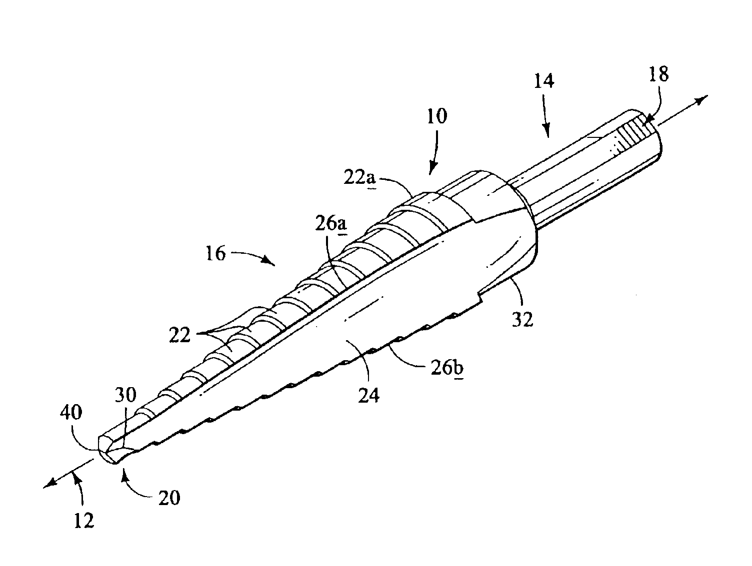
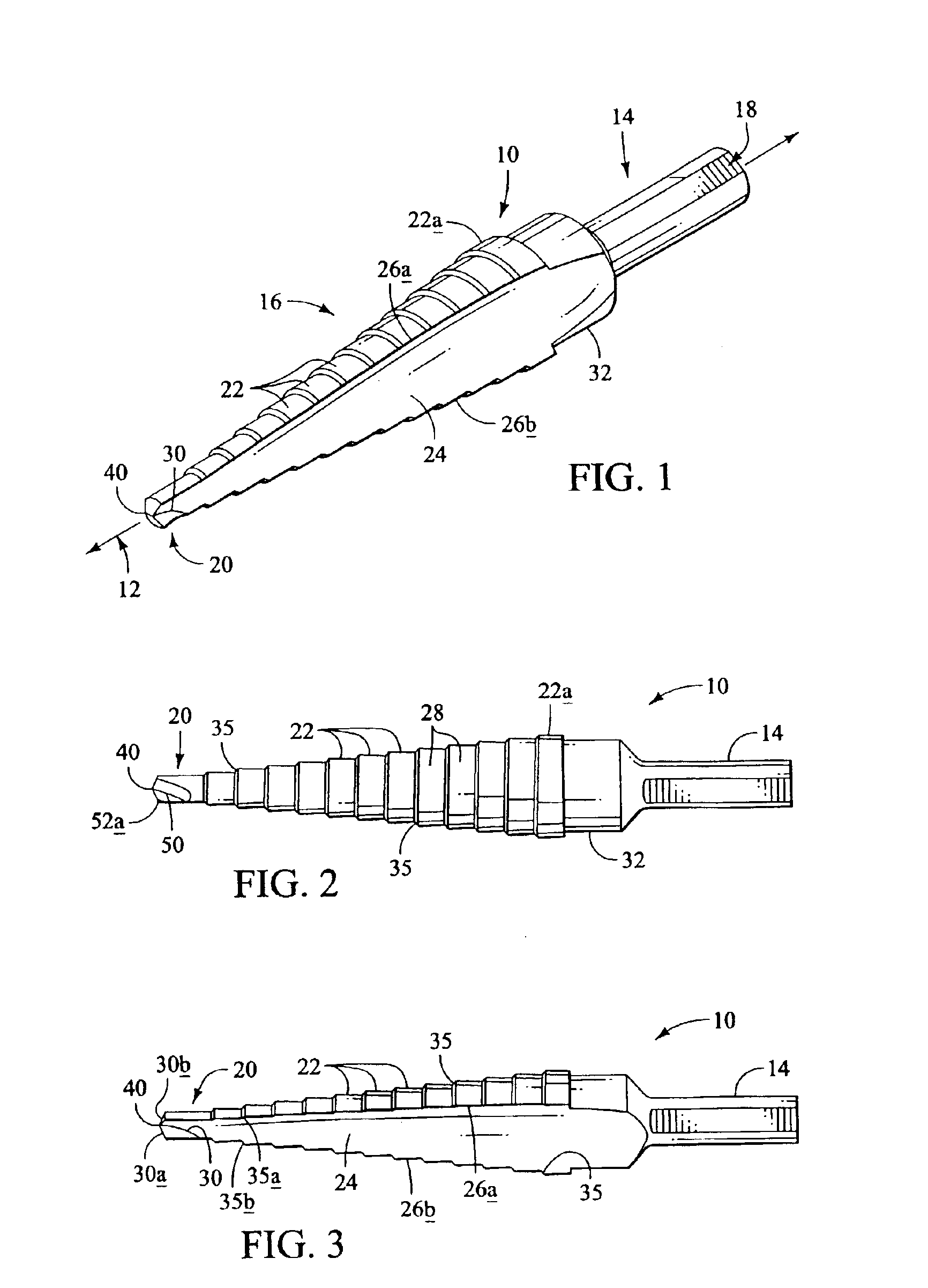
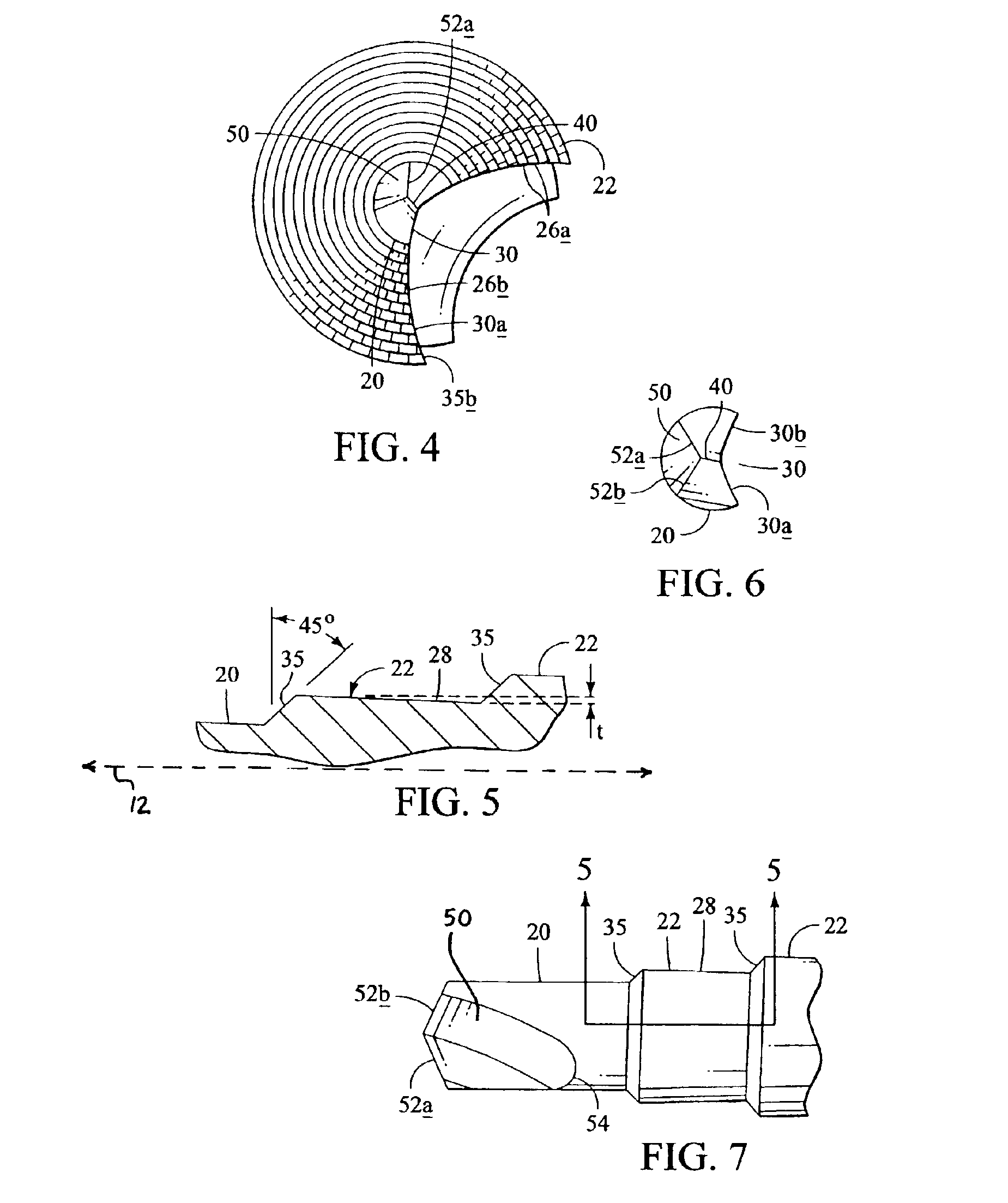
[0022]Referring now to the accompanying drawings, FIG. 1 illustrates the main conical-shaped body of a preferred embodiment of a drill bit in accordance with the present invention. In particular, the drill bit 10 is defined along a longitudinally extending axis shown in FIG. 1 at reference numeral 12. The drill bit 10 further includes a bit holding portion including an elongated cylindrical shaft 14 extending along the axis 12 and a generally conical-shaped drilling portion 16 axially aligned and adjacent to the bit holding portion 14. The bit holding portion 14 preferably defines at least one longitudinal flat surface 18 and is sized to fit within an ordinary mandrel, chuck or stock, such as ordinarily employed for holding rotating tool bits. The remainder of the shaft may be generally conical.

[0023]The main conical body of the drilling portion 16 is reduced or tapered toward a tip portion 20, which is at an end opposite the bit holding portion 14. This conical body of the drilling...


PUM

PropertyMeasurementUnit
Angleaaaaaaaaaa
Lengthaaaaaaaaaa
Angleaaaaaaaaaa

Abstract

A drill bit is disclosed having a cutting portion having a plurality of axially aligned, graduated cutting members. Each of the members has cutting edges defined by a single slot extending therethrough. A tip portion at one end of the cutting portion defines at least a pair of cutouts therein, wherein one of the cutouts is aligned with the slot.

Description

FIELD OF THE INVENTION[0001]The present invention relates to drilling and boring tools. In particular, the present invention relates to drill bits for drilling holes of varying sizes into workpieces.BACKGROUND OF THE INVENTION[0002]Conventional drill bits have been used in the past to bore holes into a workpiece. Typically, such bits position a cutting surface around an axis of the bit, and the bit is rotated at high speed around the axis using a rotary power tool such as a hand drill or a drill press. The rotating cutting edge of the bit bores a circular opening as the bit is advanced into the workpiece.[0003]Standard drill bits may be configured to be of a generally uniform radial size so that a single bit is adapted to produce a hole of a single radius. To promote space savings and to reduce the need to own a large number of standard drill bits, stepped drill configurations have been developed wherein a generally conically shaped bit includes a plurality of graduated, stepped sho...

Claims


Application Information

Patent Timeline
IPC IPC(8): B23B51/00
CPCB23B51/009B23B2251/04Y10T408/906Y10T408/03Y10T408/9065
Inventor SINGH, IQBALSCHUERMAN, HARLEY
Owner BLACK & DECKER INC
Learn More