Encoding apparatus and method, recording medium and program

a technology of coding apparatus and recording medium, applied in the field of coding apparatus and method, recording medium and program, can solve the problems of dc control not being done to keep the limitation, the same last finite state table, and the quality of servo signals deteriorating

Inactive Publication Date: 2005-05-10
SONY CORP
View PDF2 Cites 29 Cited by
  • Summary
  • Abstract
  • Description
  • Claims
  • Application Information

AI Technical Summary

Benefits of technology

[0067]It is therefore an object of the present invention to overcome the above-mentioned drawbacks of the related art by providing a coding method of converting an m-bit information word continuously into an n-bit word by inserting, into an information sequence, DC control bits for DC control of a code sequence in which ...

Problems solved by technology

Since there are many options in each of the state splitting and state merging operations, however, using the same approximate characteristic vector will not always result in the same last finite states table.
Since a low-frequency component of a read signal in a data area is superposed as a noise on the extracted servo signal if the low-frequency component of the code spectrum is not suppressed at all, the servo signal will have the quality thereof deteriorated considerably.
In the case of EFM code, however, if a certain information sequence is given continuously, any DC control cannot be done to keep the limitation on a (2, 10) RLL code and DSV of the code will not be finite in some cases.
However, since commonly used input information has a high randomness, the above will not be any practical problem.
However, a large number of DC control bits has to be inserted into a code sequence in order to keep the RLL limitation and thus the code redundancy including the influence of the DC control bits is apt to be increased.
For some codes, it is difficult to design a code conversion table with a high coding rate.
In many cases, the code conversion table is so complex that the encoder and decoder are complex in...

Method used


Image

  • Encoding apparatus and method, recording medium and program
  • Encoding apparatus and method, recording medium and program
  • Encoding apparatus and method, recording medium and program

Examples


Embodiment Construction

[0156]The present invention will be described concerning the embodiments thereof with reference to the accompanying drawings.

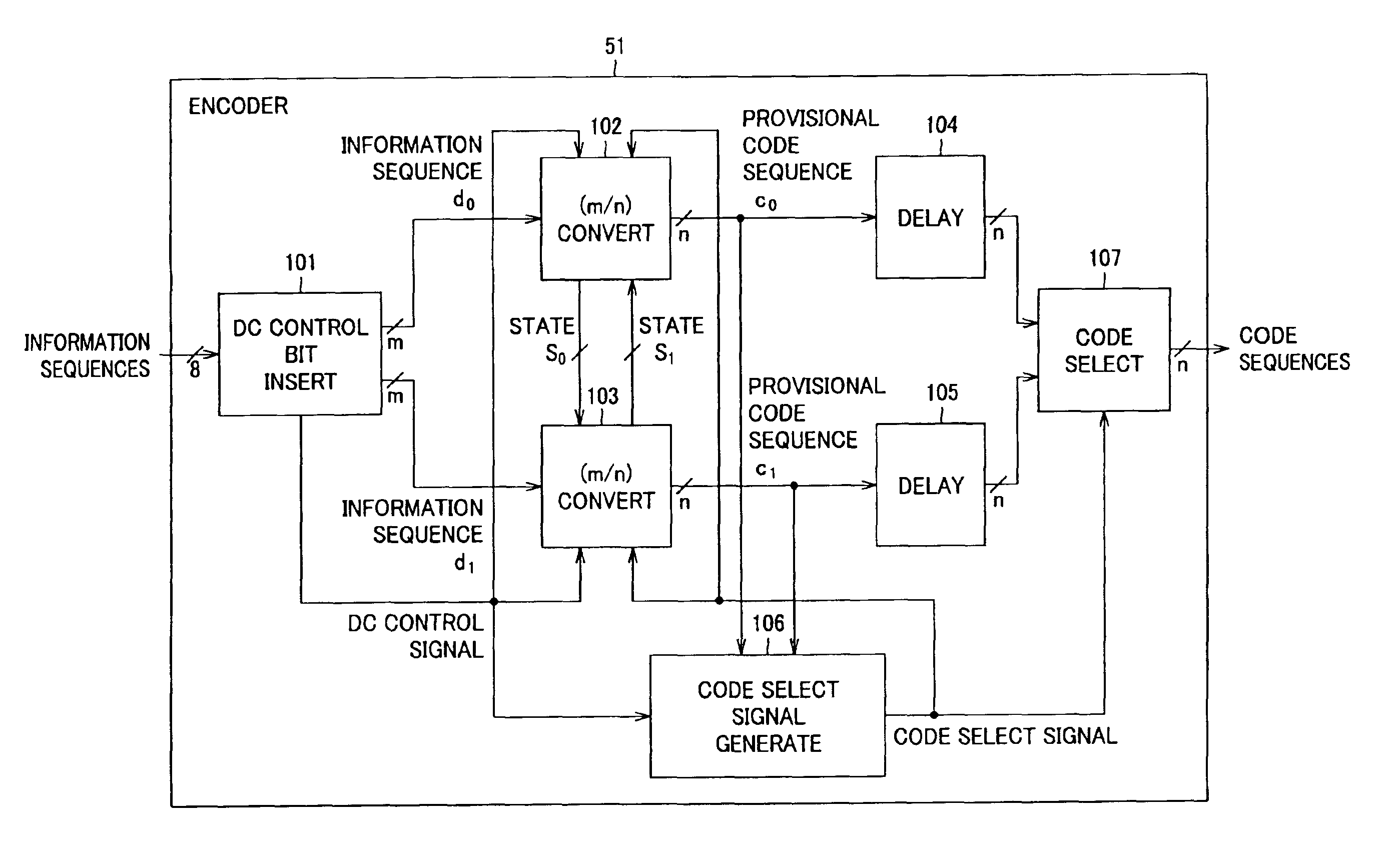
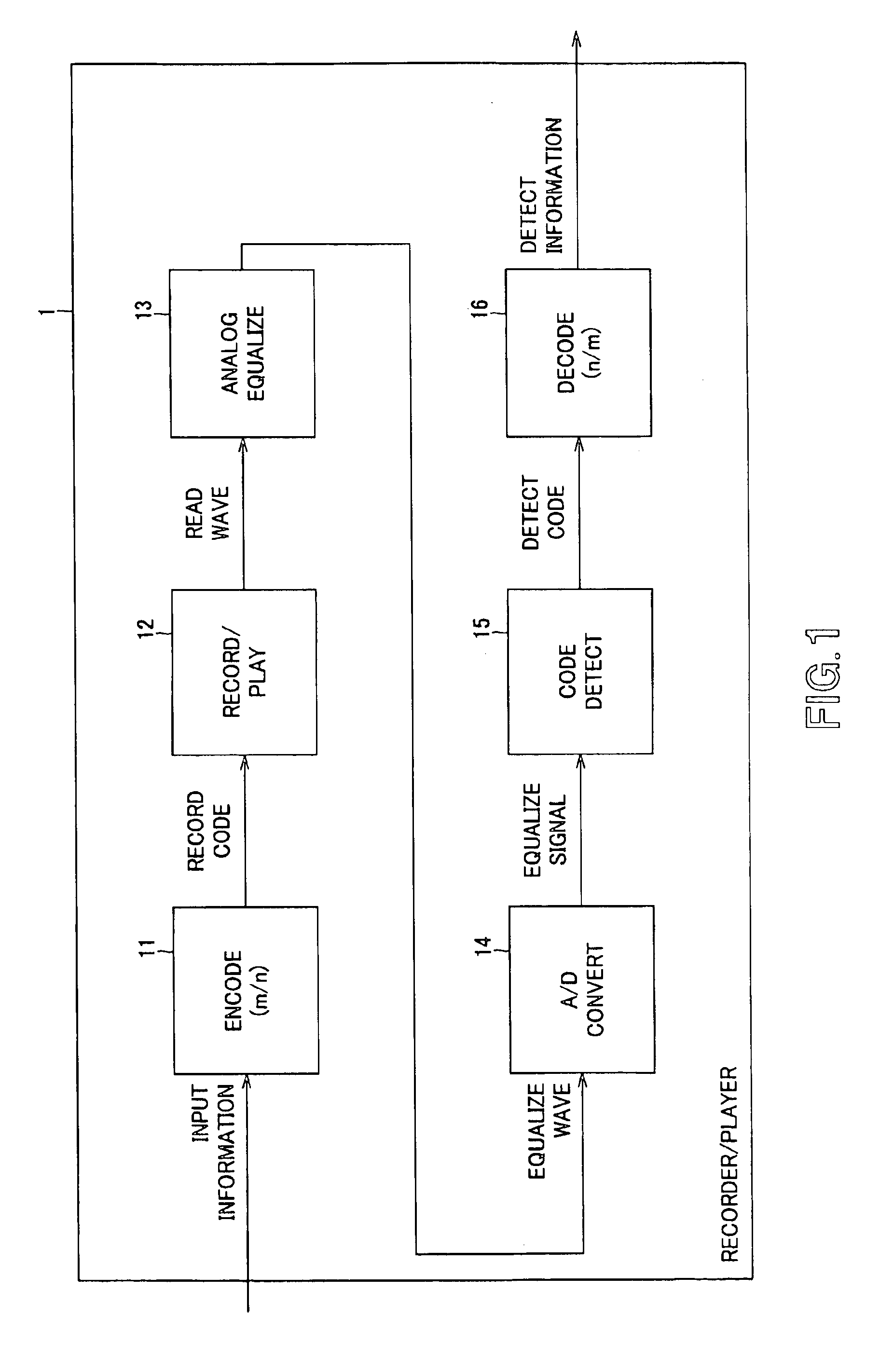
[0157]Referring now to FIG. 11, there is schematically illustrated in the form of a block diagram a recorder / player 31 according to the present invention. It should be noted that the elements of this recorder / player 31, corresponding to those of the conventional recorder / player 1 shown in FIG. 1 are indicated with the same references as those used in FIG. 1 and will not be described below wherever appropriate. As will be seen, the recorder / player 31 shown in FIG. 11 is similar in construction to the recorder / player 1 in FIG. 1 except for a coding unit 51 provided in place of the encoder 11.

[0158]The recorder / player 31 shown in FIG. 11 may be composed of two units, namely, an encoder 41 composed of the coding unit 51 and a recording / playback unit 12, and a decoder 42 composed of the recording / playback unit 12 (also used in the encoder 41), an analog equalizer 1...


PUM


Abstract

A code sequence is encoded using a code conversion table in which the parity of the code sequence varies until the code states become equal to each other. The code word assignment used in this code conversion table is such that the decoded code word constraint length is 3 blocks and q0≠q1 for an arbitrary information sequence is satisfied even if a DC control bit is inserted at any of the first and second bits of an information word. Code states s0 and s1 when information sequences d0 and d1 resulted from insertion of provisional DC control bits 1 and 0 inserted at the top of an information sequence “1, 1, 0, 0, 0, 1, 0” are encoded starting with a state 3 according to a predetermined code conversion table are equal to each other, namely, s0=s1=6, in a third block, and two's complement q0 of a sum of code sequences c0 up to a time when the code states are equal to each other is “0” while two's complement q1 of a sum of code sequences c1 up to that time is “1”. That is, the condition that q0≠q1 is met. The code sequence can be applied to a recorder/player or encoder.

Description

BACKGROUND OF THE INVENTION[0001]1. Field of the Invention[0002]The present invention generally relates to a coding apparatus and method, recording medium and a program, and more particularly to a coding apparatus and method, recording medium and a program, suitable for use in converting an m-bit information word continuously into an n-bit code word with DC control bits for DC control of a code sequence being inserted in a sequence of information.[0003]This application claims the priority of the Japanese Patent Application No. 2003-079556 filed on Mar. 24, 2003, the entirety of which is incorporated by reference herein.[0004]2. Description of the Related Art[0005]Many of various types of recorder / players and communications devices are designed for a reduced rate of errors, caused by coding of input information, of digitally transmitted information.[0006]Referring now to FIG. 1, there is schematically illustrated in the form of a block diagram a digital signal processing circuit incl...

Claims


Application Information

Patent Timeline
IPC IPC(8): G11B20/14H03M5/00H03M5/14H03M7/14
CPCG11B20/1426H03M5/145G11B2020/1457
Inventor NODA, MAKOTOYAMAGISHI, HIROYUKI
Owner SONY CORP
Why Eureka
Try Eureka