
Method of determining active priorities

a priority and active technology, applied in the field of computer graphics, can solve the problems of inefficiency of removing an object and associated priority value from a sorted priority list, deteriorating method performance, and inability to improve the method of marking objects

Inactive Publication Date: 2005-05-10
CANON KK
View PDF3 Cites 41 Cited by
  • Summary
  • Abstract
  • Description
  • Claims
  • Application Information

AI Technical Summary

Benefits of technology

[0040]It is an object of the present invention to substantially overcome,

Problems solved by technology

Although this known method of rendering an image is suitable for small numbers of active objects, performance for the method deteriorates markedly when a large number of objects are activated simultaneously.
Hence, removing an object and associated priority value from a sorted priority list is inefficient if the object must be reinserted again at a later time.
However, the method of marking objects does not improve performance when a large number of objects are activated simultaneously as discussed above.
However, the disadvantage of this still further method is the complexity of sorting the linked list of objects and associated priority values.
Further, this method of adding a priority object to the head of a priority list requires a large amount of memory since ideally such a method uses a doubly linked list requiring a next pointer and a previous pointer.
One problem of the method of setting each object in an active priority list as TRUE or FALSE is that the method is required to perform a large number of memory accesses.
However, a significant speed penalty is still incurred using this one bit method, since a potentially large number of object entries may still be required to be traversed in order to find the opaque object having highest associated priority value.

Method used


Image

  • Method of determining active priorities
  • Method of determining active priorities
  • Method of determining active priorities

Examples


Embodiment Construction

[0079]Where reference is made in any one or more of the accompanying drawings to steps and / or features, which have the same reference numerals, those steps and / or features have for the purposes of this description the same function(s) or operation(s), unless the contrary intention appears.

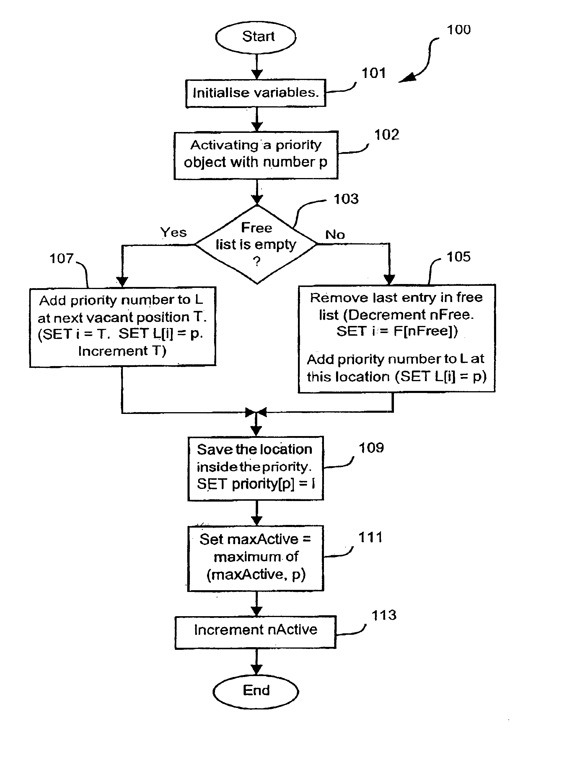
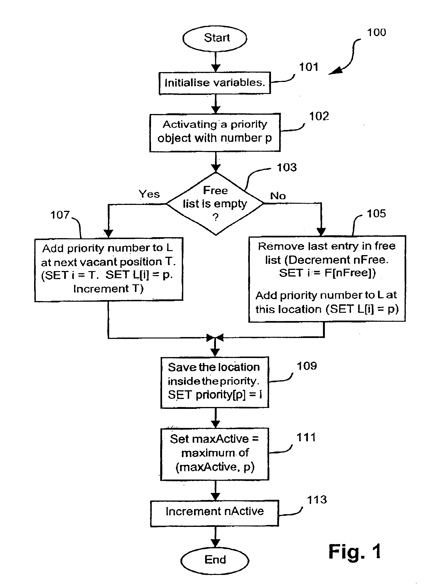
[0080]FIG. 3 is a flow diagram showing a method 300 of determining active objects contributing to a run of pixels corresponding to a scanline. The method 300 is preferably practiced using a general-purpose computer system 1000, such as that shown in FIG. 10 wherein the described method 300 can be implemented as software, such as an application program executing within the computer system 1000. In particular, the steps of the described method 300 are effected by instructions in the software that are carried out by a processor 1005 of the computer system 1000. The instructions may be formed as one or more code modules, each for performing one or more particular tasks. The software may also be divided...


PUM


Abstract

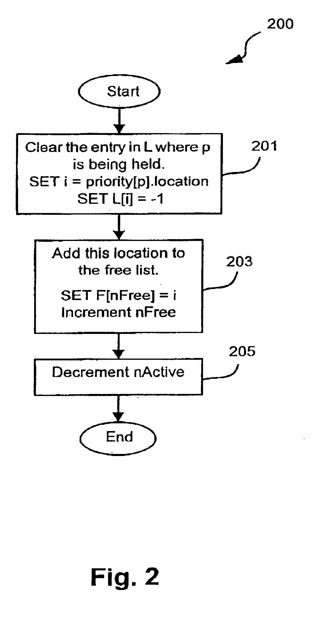
A method (300) and apparatus (1000) for determining active objects contributing to a run of pixels corresponding to a scanline is disclosed. The method 300 utilizes two memory (1006) integer arrays (1101) and (1102) of size N, where N represents the number of objects in a job to be rendered. The first array (1101) is an active priority list and is preferably stored in memory (1006). The first array (1101) will be hereinafter referenced as the ‘active priority list (i.e. L[ ])’. The second array (1102) is an array of pointers (i.e. indexes) that indicate vacant memory 1006 locations in the active priority list (1101), when an object is deactivated. The second array (1102) will be hereinafter referred to as a ‘free list (F[ ])’ and is also preferably stored in memory (1006). The active priority list (1101) and free list (1102) can be stored at consecutive memory (1006) addresses (e.g. Memory address 0 to memory address 2N) or alternatively, the active priority list (1101) and free list (1102) can be stored in any suitable free memory (1006) locations.

Description

TECHNICAL FIELD OF THE INVENTION[0001]The present invention relates generally to computer graphics and, in particular, to a method of determining which graphical objects are active at an edge-crossing for any given scan-line of a graphics rendering system. The invention also relates to a computer program product including a computer readable medium having recorded thereon a computer program for determining which graphical objects are active at an edge-crossing for any given scan-line of a graphics rendering system.BACKGROUND ART[0002]Software application programs, such as word processors, are generally configured to create page-based documents where each page contains document data such as graphical objects (e.g. text, images), represented by lines and fill regions. When representing the document data on a display device or a printing device, such software application programs generally use the graphics interface services of a host operating system to send commands describing graphi...

Claims


Application Information

Patent Timeline
IPC IPC(8): G06T11/60G06T1/20
CPCG06T11/60G06T1/20
Inventor SMITH, DAVID CHRISTOPHER
Owner CANON KK
Learn More