
Pro-active antenna switching based on relative power

a technology of relative power and antenna switching, applied in diversity/multi-antenna systems, digital transmission, polarisation/directional diversity, etc., can solve problems such as multipath fading, rf communication systems, and reducing the strength or amplitude of received signals

Inactive Publication Date: 2005-05-10
GE MAGTE MEDICAL SYST
View PDF7 Cites 70 Cited by
  • Summary
  • Abstract
  • Description
  • Claims
  • Application Information

AI Technical Summary

Benefits of technology

"The present invention is about a system and method for switching antenna fields without waiting for data packets with errors to be detected. It monitors signal power for each antenna field and switches to another antenna field with greater signal power even if error-free data packets had been received via the previous antenna field. This results in a more efficient and faster switching process. The invention also introduces time periods when no data is being transmitted and uses these periods to estimate signal power for each antenna field. This allows the receiver to switch to the most appropriate antenna field based on highest signal power without interruption. The invention can be used in a patient monitoring environment or any RF communications system."

Problems solved by technology

Multipath fading is a well-known problem that affects many RF communications systems.
These out-of-phase received signals, when combined, will at least partially cancel each other, thereby reducing the strength or amplitude of the received signal.
This problem is especially acute for indoor communications systems because of the large number of reflections that can occur in the indoor environment.
This is caused by blockage of the RF propagation by a large obstruction, and it results in lowering of the mean received signal power.
This results in lost data due to reception errors, alternate antenna field testing, and antenna switching time.
The errors in the known system described above are due to the fact that now such prediction is not attempted.
Such prediction is not possible in the known system because incoming monitoring data consumes all the bandwidth of the channel.

Method used


Image

  • Pro-active antenna switching based on relative power
  • Pro-active antenna switching based on relative power
  • Pro-active antenna switching based on relative power

Examples


Embodiment Construction

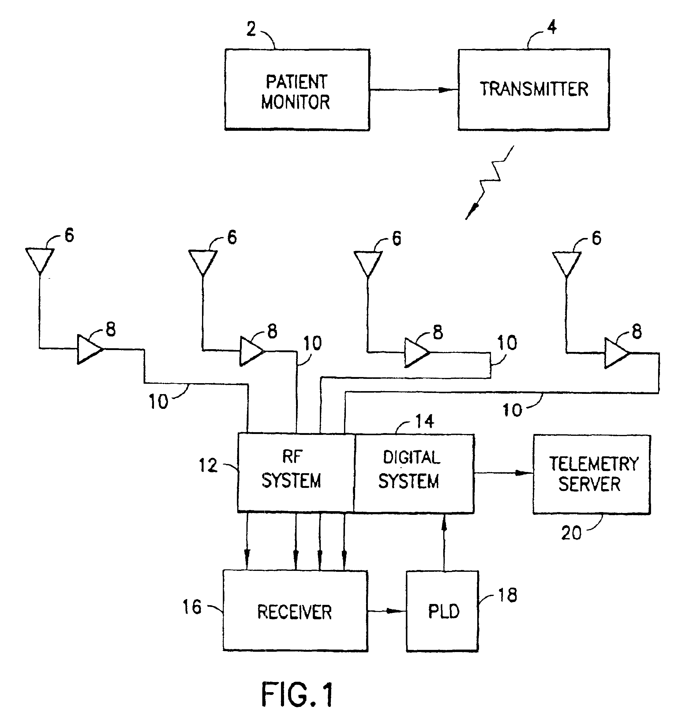
[0016]In accordance with the preferred embodiment of the invention shown in FIG. 1, a multiplicity of patients in a hospital can be remotely monitored using portable patient monitors, each patient monitor 2 having an antenna and a transmitter 4 for transmitting acquired patient monitoring data to a central receiving office or station via a plurality of receiving antennas 6.

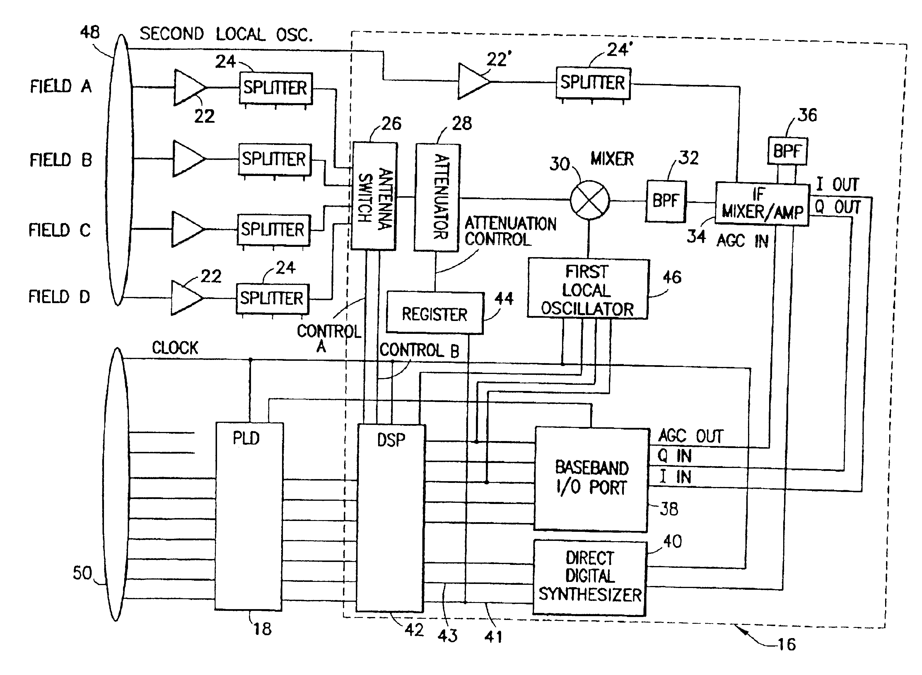
[0017]In one exemplary implementation of the preferred embodiment, the hospital area is covered by four overlapping antenna fields (one for each of antennas 6 shown in FIG. 1) which are ganged to the same central receiving office or station. Each antenna field is coupled to a receiver subsystem via a respective antenna amplifier 8 and coaxial cable 10. As shown only generally in FIG. 1, the receiver subsystem comprises an RF system 12 and a digital system 14. The receiver subsystem provides an interface between individual receiver modules 16 (only one of which is depicted in FIG. 1) and a telemetry server 20 conne...


PUM


Abstract

A system and a method for switching antenna fields without waiting until data packets containing errors are detected. This is accomplished by monitoring the signal power for each antenna field immediately after receipt of data packets via the currently active antenna field and then switching to another antenna field having greater signal power. A communications channel is provided which has a capacity greater than that required by the data to be transmitted. This extra capacity is used to introduce time periods when no data is being transmitted. During these time periods, known bit patterns are transmitted, and the signal power during receipt of each of these blank packets is estimated for each antenna field. The receiver then switches to the most appropriate antenna field based on highest signal power (e.g., based on a weighted average for the N-th most recent sample periods) and continues to receive the transmitted data without interruption.

Description

FIELD OF THE INVENTION[0001]This invention generally relates to systems and methods for wireless communication between mobile units and a stationary central office or station. In particular, the invention relates to systems and methods for wireless transmission of data from mobile data acquisition units to a stationary central receiver.BACKGROUND OF THE INVENTION[0002]Multipath fading is a well-known problem that affects many RF communications systems. Fading occurs when multiple, out-of-phase versions of a narrowband RF transmission arrive at the receive antenna simultaneously, usually as a result of multiple reflections of the transmission. These out-of-phase received signals, when combined, will at least partially cancel each other, thereby reducing the strength or amplitude of the received signal. This problem is especially acute for indoor communications systems because of the large number of reflections that can occur in the indoor environment.[0003]Another effect observed in ...

Claims


Application Information

Patent Timeline
Patent Type & Authority Patents(United States)
IPC IPC(8): H04B7/08
CPCH04B7/0811
Inventor HURLEY, JAMES PATRICKHOCTOR, RALPH THOMAS
Owner GE MAGTE MEDICAL SYST
Learn More