Echo canceller

Inactive Publication Date: 2005-05-10
OKI ELECTRIC IND CO LTD
View PDF2 Cites 6 Cited by
  • Summary
  • Abstract
  • Description
  • Claims
  • Application Information

AI Technical Summary

Benefits of technology

[0024]In order to solve these problems, the echo canceller of this invention is an echo canceller which forms a pseudo-echo signal from a reception signal using an adaptive filter, subtracts the pseudo-echo signal from the transmission signal using a subtractor, and eliminates the echo component in the transmission signal. The echo canceller of this invention has a holding portion to hold at least a communication frame length's worth of the reception signal;

Problems solved by technology

However, in the above echo canceller example of the prior art, the tap coefficients Hk(n) are calculated using equations (3) and (4), and so the following problems arise from the large amount of calculations.
Because this preprocessing is also executed by the DSP as part of the division operation, there is the problem that even a single division operation can impose an extremely large burden on the DSP.
However, if division is performed each time a delay sample is introduced, a large part of the allowed calculation amount will be consumed by division operations.
Hence there is the problem that a large calculation capacity cannot be left for the above-described vital multiply-accumulate operations.

Method used


Image

  • Echo canceller
  • Echo canceller
  • Echo canceller

Examples


first embodiment

[0044](A) First Embodiment

[0045](A-1) Configuration of the First Embodiment

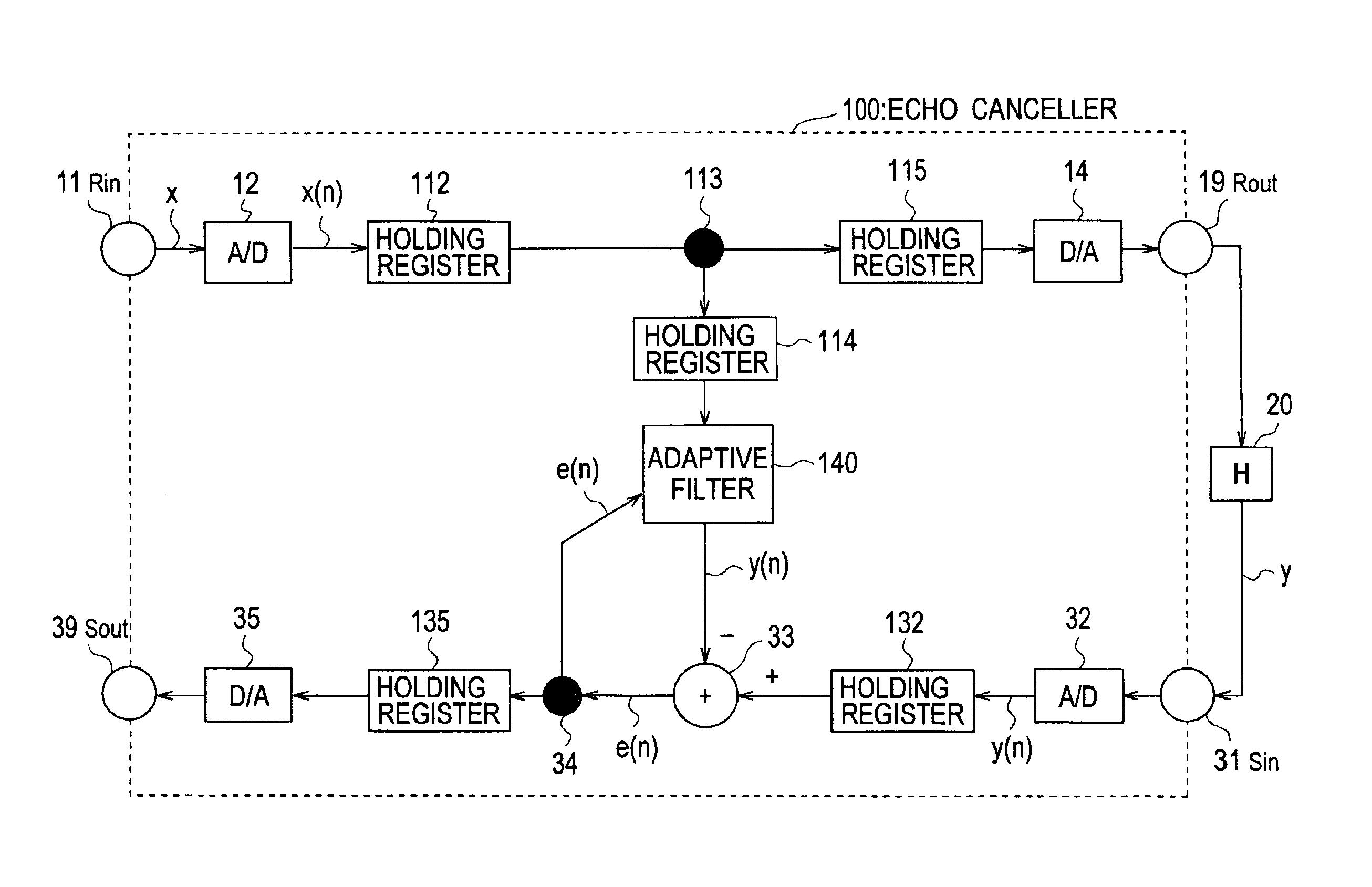
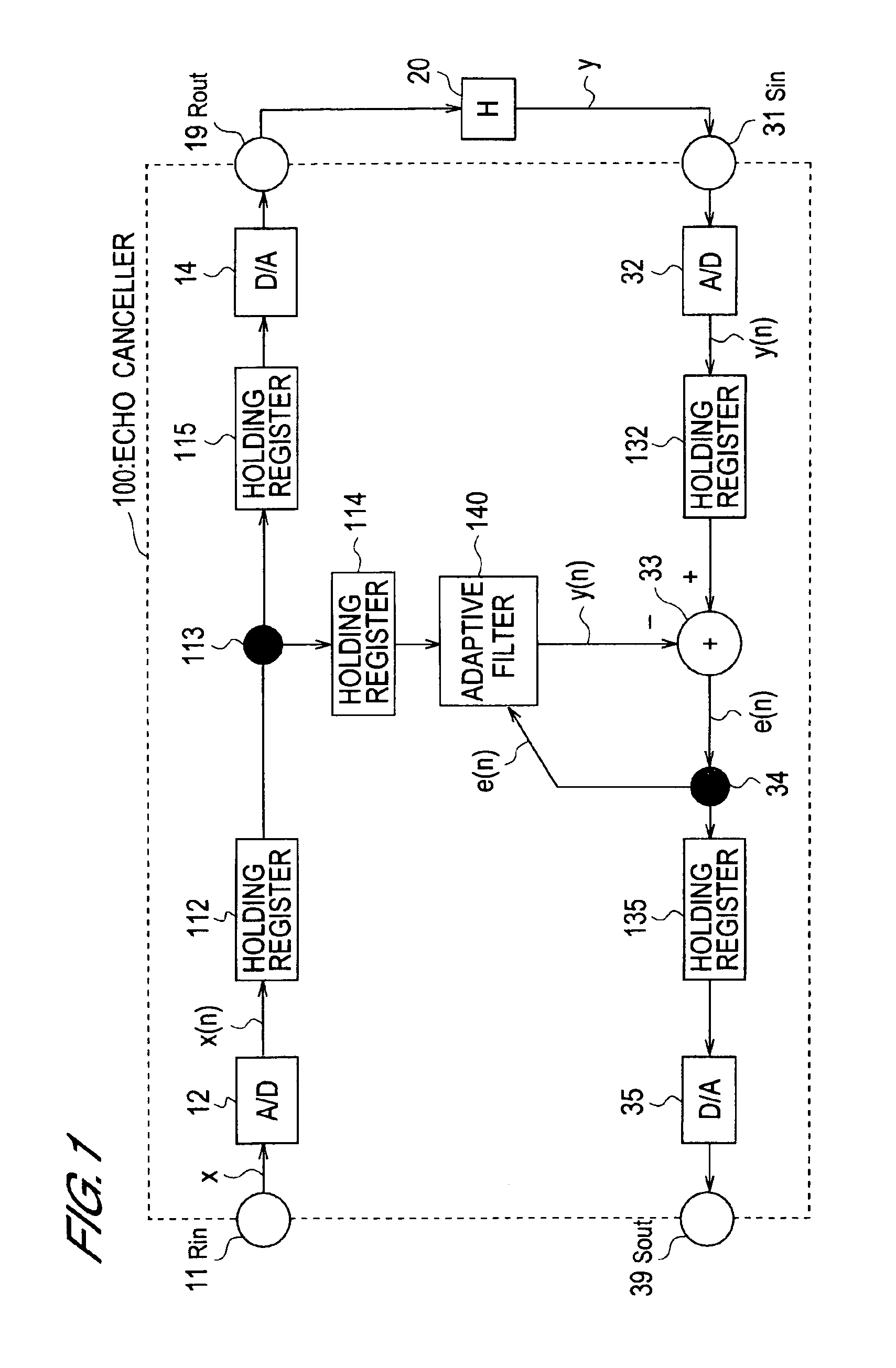
[0046]The echo canceller of the first embodiment is a device having a holding register for the delay sample signal train in the reception input route; its functions are indicated in the block diagram of FIG. 1.

[0047]In FIG. 1, this echo canceller 100 has a reception signal route and a transmission signal route. The reception signal route comprises a reception input terminal Rin 11, connected to an exchange network; an analog / digital (A / D) converter 12 for reception signals; a holding register 112 for a train of digital reception signals X(n); an input reference point 113 for an adaptive filter 140, described below; separate holding registers 114, 115 for similar trains of reception signals X(n); a digital / analog (D / A) converter 14; and a reception output terminal Rout 19.

[0048]The transmission signal route comprises a transmission input terminal Sin 31; another A / D converter 32; still another holding register...

second embodiment

[0062](B) Second Embodiment

[0063](B-1) Configuration of the Second Embodiment

[0064]The second embodiment is an echo canceller with improved echo elimination processing speed through a separate adaptive filter 240. A delay sample signal X(n) train is introduced into this separate adaptive filter 240 from a holding register 114, and the power signal is determined by a separate power calculation portion 252; otherwise, the device is similar to that of the first embodiment. An example of the functions of the adaptive filter 240 is shown in the block diagram of FIG. 7.

[0065](B-2) Operation of the Second Embodiment

[0066]In the second embodiment, a train of 80 delay sample signals X(J,0) to X(J,79) is introduced into and stored in the holding register 114 for each frame of reception signals, as shown in FIG. 8. From a train of 128 delay sample signals including the above signals, the power signal POWER_BL(J,n) is calculated by the power calculation portion 252.

[0067]POWER_BL(J,0) to POWER_...

third embodiment

[0072](C) Third Embodiment

[0073](C-1) Configuration of the Third Embodiment

[0074]The third embodiment is an echo canceller in which still another adaptive filter 340 prevents biasing of the echo elimination performance relative to the preceding and following frames; by means of a smoother (LPO) 355 added to the previous stage of the coefficient update portion 350 of this separate adaptive filter 340, the power signal is smoothed; otherwise, the device is similar to that of the second embodiment. An example of the functions of the adaptive filter 340 is shown in the block diagram of FIG. 9.

[0075](C-2) Operation of the Third Embodiment

[0076]In this third embodiment, the power signal POWER_BL(J) calculated by the power calculation portion 352 is introduced into the smoother 355, and smoothing is performed using the following equation (11). Here δ is a constant in the range 0<δ<1 which determines the extent of the smoothing; the larger the value of δ, the faster the changes in POWER_BL(...


PUM


Abstract

The present invention provides an echo canceller having a holding portion which holds at least a communication frame length's worth of reception signals; a power calculation portion which calculates power for each communication frame based on the reception signals held in this holding portion; a divider which divides, by the power calculated for each communication frame, the echo elimination residue signal for each sample of the communication frame output from a subtractor; and an update portion which updates the tap coefficients of an adaptive filter according to the output signals from the divider.

Description

BACKGROUND OF THE INVENTION[0001]1. Field of the Invention[0002]This invention relates to an echo canceller based on a prescribed echo model.[0003]2. Description of Related Art[0004]In general receiver terminal devices, an audio signal from an exchange network is introduced via a four-line circuit, and this is supplied to many types of service by a two-line circuit. At the termination of such a communication circuit, various echo cancelling techniques are used in order to deal with impedance mismatching. These techniques are disclosed in the reference “Introduction to Adaptive Filters”, S. Haykin, Macmillan Publishing Co., New York, and elsewhere.[0005]For example, there is a technique which uses an echo canceller with the configuration shown in the block diagram of FIG. 2. In FIG. 2, this echo canceller 10 which is an example of the conventional art has a receiving signal route comprising a reception input terminal Rin 11 for reception from the exchange network, an analog / digital c...

Claims


Application Information

Patent Timeline
IPC IPC(8): H04B3/23H04M9/08H04Q3/42H04M1/60
CPCH04M9/082H04B3/23
Inventor TAKADA, MASASHISHIMBO, ATSUSHI
Owner OKI ELECTRIC IND CO LTD
Why Eureka
Try Eureka