Reinforcement structure of truss bridge or arch bridge

a technology of reinforcement structure and truss bridge, which is applied in the direction of bridges, bridge structural details, arch-type bridges, etc., can solve the problems of increasing working costs, many reinforcement plates, and long time-consuming work, and achieve the effect of inducing a load resisting for

Inactive Publication Date: 2005-05-17
ASAHI ENG CO LTD +2
View PDF24 Cites 15 Cited by
  • Summary
  • Abstract
  • Description
  • Claims
  • Application Information

AI Technical Summary

Benefits of technology

[0008]It is, therefore, an object of the present invention to provide a reinforcement structure of a truss bridge or an arch bridge, in which, through co-action between auxiliary triangular structural frames which are each constructed at opposi

Problems solved by technology

However, the above-mentioned reinforcement work requires such troublesome work that many reinforcement plates are needed and each sheet must be bolted.
In addition, a long period of time is required for the work and working costs are increased.
When t

Method used


Image

  • Reinforcement structure of truss bridge or arch bridge
  • Reinforcement structure of truss bridge or arch bridge
  • Reinforcement structure of truss bridge or arch bridge

Examples


Embodiment Construction

[0025]Embodiments of a reinforcement structure of a truss bridge or arch bridge according to the present invention will be described hereinafter with reference to FIG. 1 through FIG. 11.

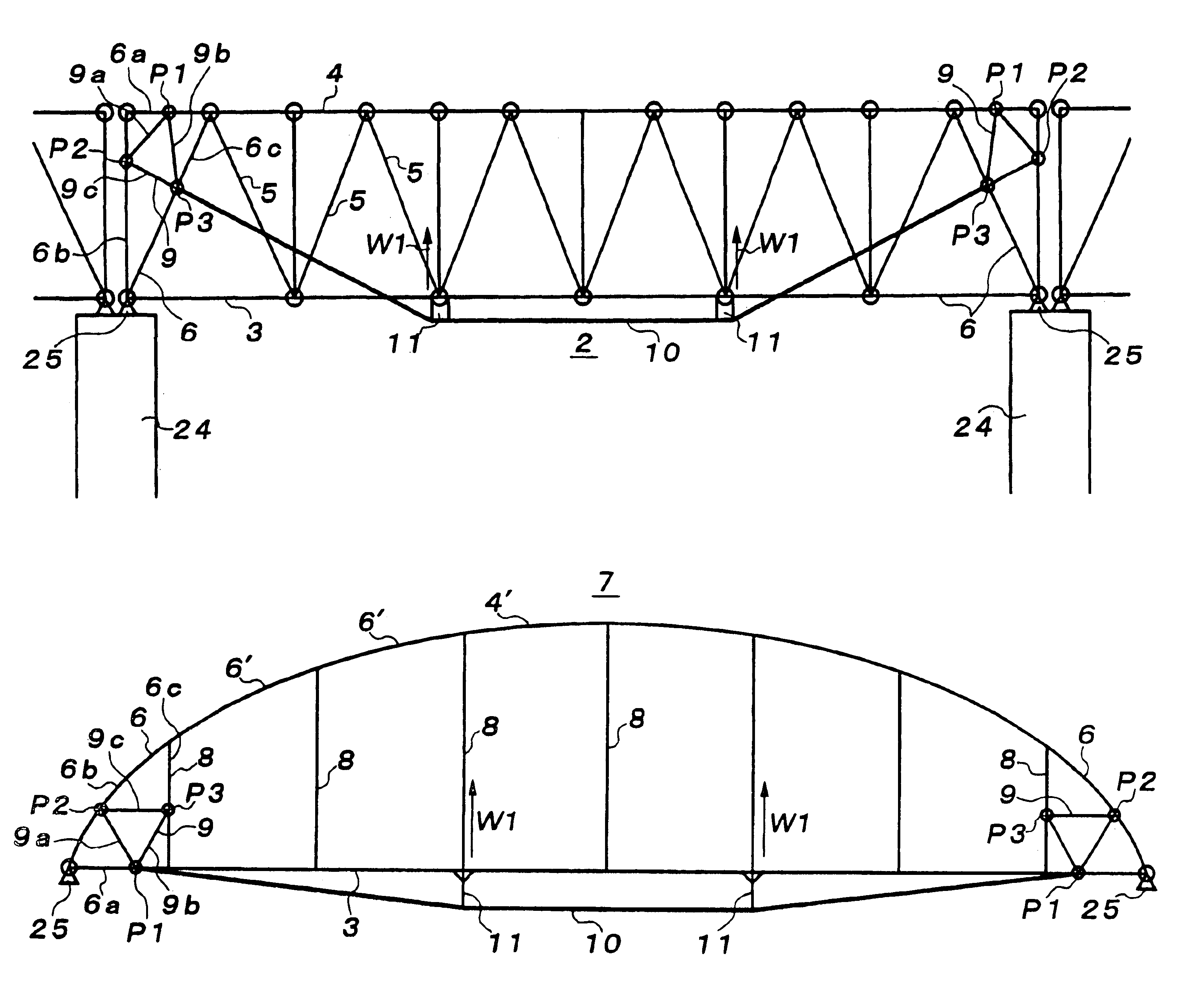
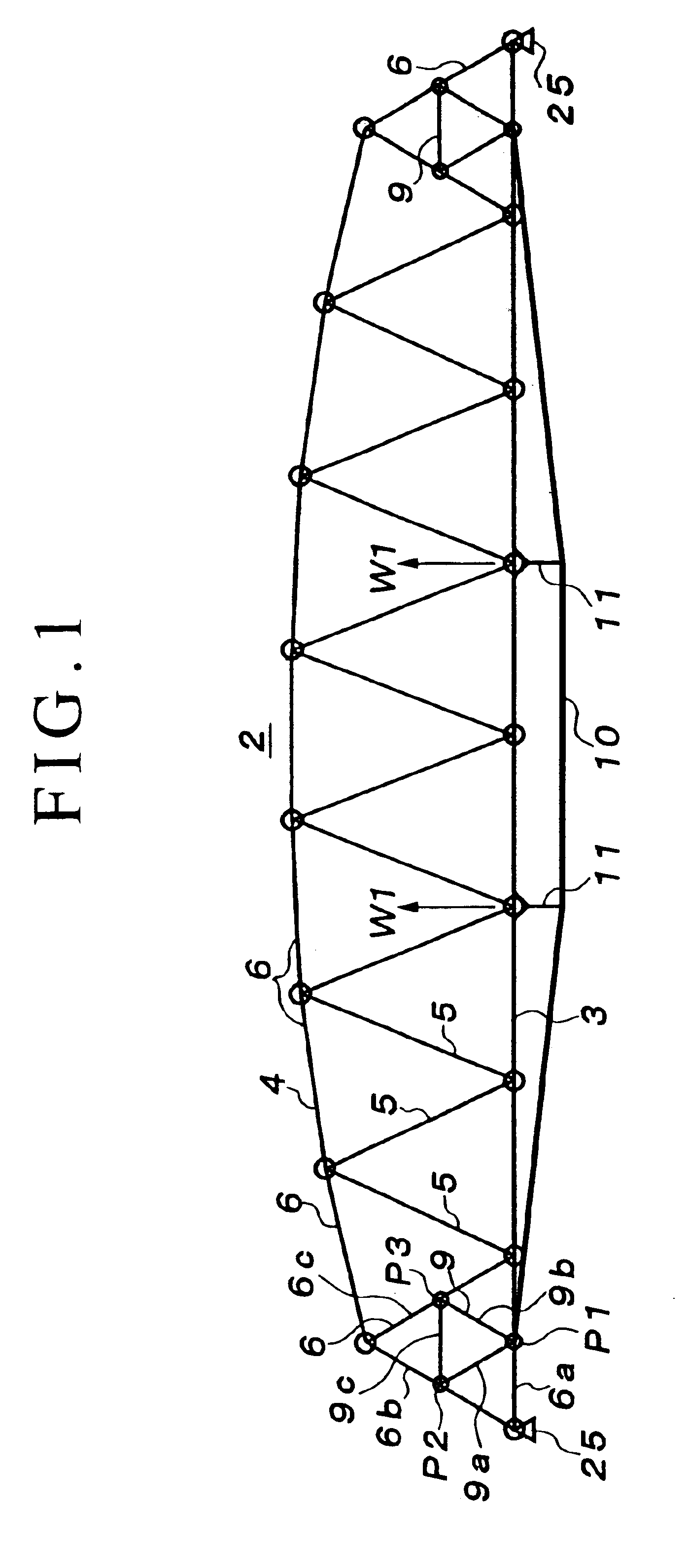
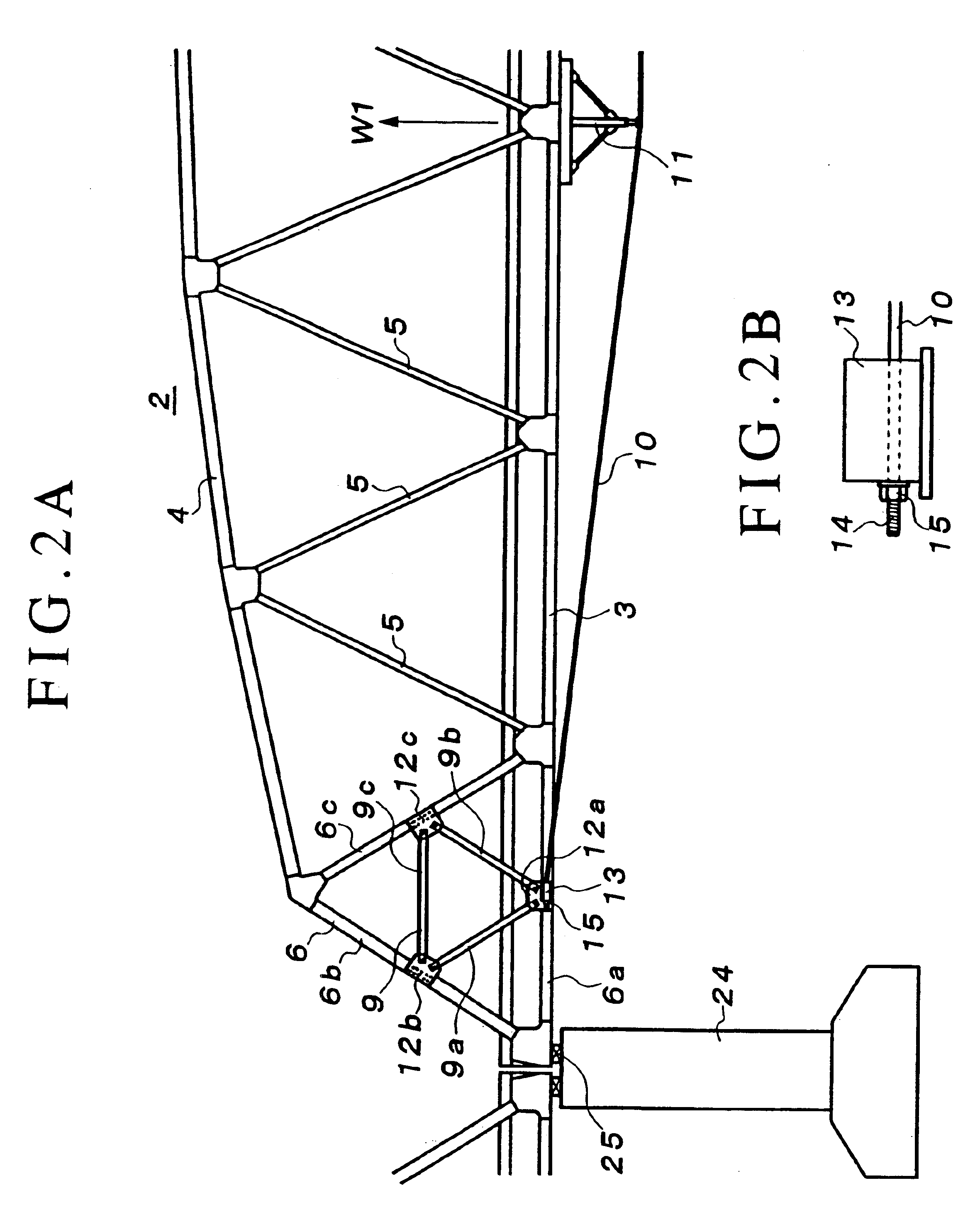
[0026]As shown in FIGS. 1 through 7, a truss bridge is a bridge having two truss girders 2, each of which is constructed on each side in a sense of a road width direction of a floor slab 1. Each truss girder 2 has a structure in which a lower chord 3 and an upper chord 4 are joined by a plurality of diagonal members 5 which are inserted therebetween in a zigzag manner, thereby forming a plurality of main triangular frames 6 from one end of the truss girder 2 to the other end thereof.

[0027]On the other hand, as shown in FIGS. 8 through 10, an arch bridge is a bridge having two arch girders 7, each of which is constructed on each side in a sense of a road width direction of a floor slab 1. The arch bridge has a structure in which a lower chord 3 and an arch member 4′ are joined by a plurality of vertic...


PUM


Abstract

Through co-action between auxiliary triangular structural frames, which are each constructed at opposite ends of a truss girder or arch girder, and a cable stretched between the auxiliary triangular structural frames, an upwardly directed force is exerted to the truss girder or arch girder, thereby effectively inducing a load resisting force. A reinforcement structure of a truss bridge or arch bridge is comprised of a truss girder or arch girder, a first and a second end of which are each provided with a main triangular structural frame. The main triangular structural frame is provided at an inner side thereof with an auxiliary triangular structural frame. The auxiliary triangular structural frame is joined at vertexes thereof with frame structural elements at respective sides of the main triangular structural frame. A cable extends in a longitudinal direction of the truss bridge, being stretched between a nearby part of a joined part at one of the vertexes of the auxiliary triangular structural frame on a side of the first end of the truss girder or arch girder and a nearby part of a joined part at a corresponding one of the vertexes of the auxiliary triangular structural frame on a side of the second end of the truss girder or arch girder. Deflecting structure, adapted to exert a downwardly directed force to the cable, is inserted between the cable and a lower chord of the truss girder or arch girder so as to tension the cable, and an upwardly directed force is exerted to the lower chord by a reaction force attributable to tension of the cable via the deflecting structure.

Description

BACKGROUND OF THE INVENTION[0001]1. Field of the Invention[0002]This invention relates to a reinforcement structure effective for improving a load resisting force of a truss bridge or an arch bridge constructed over a river or on land.[0003]2. Related Art[0004]There has heretofore been known, as a work for reinforcing a truss bridge or an arch bridge, a method in which a structural frame(s) of a truss girder or an arch girder, which constitutes the truss bridge or arch bridge, (more specifically, an upper chord, a lower chord and a diagonal member in the truss girder or a lower chord and a vertical member in the arch girder), are abutted and overlaid by a short reinforcement member and bolted together, so that a sectional area of each structural frame is increased to thereby enhance a load resisting force.[0005]However, the above-mentioned reinforcement work requires such troublesome work that many reinforcement plates are needed and each sheet must be bolted. In addition, a long pe...

Claims


Application Information

Patent Timeline
IPC IPC(8): E01D1/00E01D22/00E01D6/00E01D4/00
CPCE01D1/005E01D22/00E01D6/00
Inventor TOKUNO, MITSUHIROSAITO, FUMIHIROTAKESHIMA, SEIONAKAI, YOSHIAKI
Owner ASAHI ENG CO LTD
Why Eureka
Try Eureka