Complex motion toothbrush
a toothbrush and complex technology, applied in the field of toothbrushes, can solve the problems of not adequately cleaning the spaces between teeth, the means disclosed for providing it is far too complicated and involves far too many moving parts, and the single brushing action may be inadequate in some brushing applications, so as to achieve the effect of simple and economical
- Summary
- Abstract
- Description
- Claims
- Application Information
AI Technical Summary
Benefits of technology
Problems solved by technology
Method used
Image

Examples
second embodiment
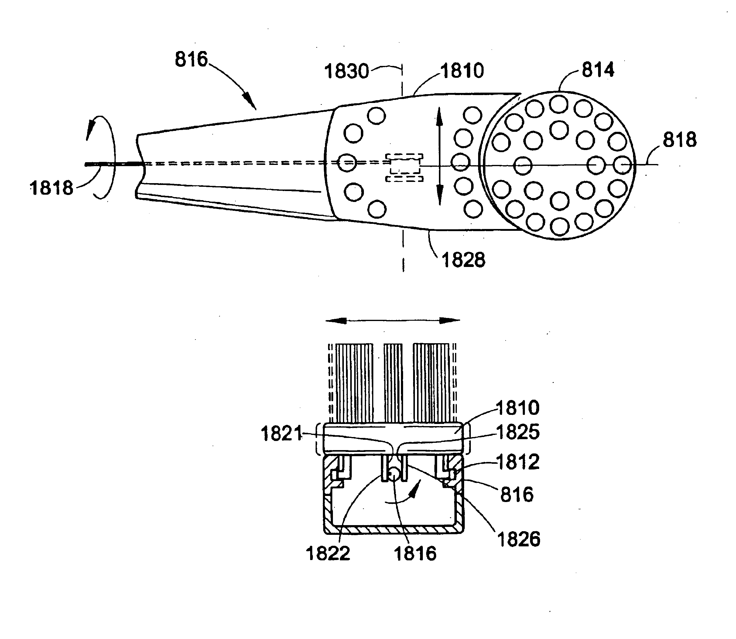
[0047]Referring to FIG. 10, in the enhanced toothbrush 810 a second bristle holder 1010 is movably mounted in slots 1012 in the toothbrush head 816 and separately driven in a vibratory, swinging or pivoting motion about a hinge or pivot 1014, by a cam 1016 included on a driving shaft 1018. The cam 1016 can comprise one or more bends in the shaft 1018 or be provided as a separate piece as previously discussed. Optionally, the driving shaft is supported by a shaft support 1020. A cam contact surface 1022 is located on a bottom surface of the second bristle holder 1010. As the motor 819 of the enhanced toothbrush 810 rotates the shaft 1018, the cam 1016 comes into contact with the cam contact surface 1022 and drives or pushes the second bristle holder 1010 causing the second bristle holder to swing or pivot about the hinge or pivot 1014. As the shaft 1018 continues to rotate, the cam 1016 becomes disengaged with the cam contact surface 1022. During use, as the cam 1016 comes in contact...
third embodiment
[0048]Referring to FIG. 11, in the enhanced toothbrush 810 a second bristle holder 1110 is movably mounted in slots 1112 in the toothbrush head 816 and separately driven in a vibratory, lifting or vertical pulsating motion (e.g., in a direction substantially perpendicular to the longitudinal axis 1114 and substantially parallel to a surface 1115 of the second bristle holder 1110 as shown by way of example in FIG. 11) within the slots 1112, by a cam 1116 included on a driving shaft 1118. Optionally, the driving shaft is supported by a shaft support 1120. The cam 1116 can comprise one or more bends in the shaft 1118 or can be provided as a separate piece as previously discussed. A cam contact surface 1122 is located on a bottom surface of the second bristle holder 1110. As the motor 819 (see FIG. 8) of the enhanced toothbrush 810 rotates the shaft 1118, the cam 1116 comes into contact with the cam contact surface 1122 and drives or lifts, in a vibratory, lifting, or vertical pulsating...
fourth embodiment
[0049]Referring to FIG. 12, in the enhanced toothbrush 810 a second bristle holder 1210 is movably mounted in slots (not shown, but similar to the slots 912 illustrated in FIG. 9) in the toothbrush head 816 and separately driven in a reciprocating or translating, longitudinal motion within the slots by a cam 1216 included on a driving shaft 1218. Optionally, the shaft is supported by shaft supports 1217. The shaft supports may include C or U shaped portions (not shown) that are operative to receive and snap around the shaft. Other means for retaining a shaft in a support are known in the art. The cam 1216 can comprise a shaped bead, with an appropriate eccentric configuration, placed or molded over and firmly secured to the shaft 1218. In one embodiment, the cam 1216 includes a pair of acutely angled surfaces 1219, 1220 which are inclined in the same direction and at the same angle of inclination, but which are disposed at opposite ends of the cam 1216. The direction of inclination ...
PUM
 Abstract
Description
Claims
Application Information
 - Generate Ideas
- Intellectual Property
- Life Sciences
- Materials
- Tech Scout
- Unparalleled Data Quality
- Higher Quality Content
- 60% Fewer Hallucinations
Browse by: Latest US Patents, China's latest patents, Technical Efficacy Thesaurus, Application Domain, Technology Topic, Popular Technical Reports.
© 2025 PatSnap. All rights reserved.Legal|Privacy policy|Modern Slavery Act Transparency Statement|Sitemap|About US| Contact US: help@patsnap.com