Dynamically-controlled cushioning system for an article of footwear

Inactive Publication Date: 2005-05-17
NIKE INC
View PDF68 Cites 76 Cited by
  • Summary
  • Abstract
  • Description
  • Claims
  • Application Information

AI Technical Summary

Benefits of technology

[0020]The present invention is a cushioning system for an article of footwear that includes a fluid-filled bladder having a plurality of separate sealed cushioning chambers. Separate reservoir chambers can also be placed in fluid communication with the cushioning chambers. The chambers are in fluid communication with each other, and a control device dynamically-distributes and regulates pressure within the chambers based on sensed and user input criteria by modulating the lev

Problems solved by technology

Moreover, physical differences between wearers of a specific shoe, such as differences in each user's weight, foot size, shape, activity level, and walking and running style, make it difficult to economically optimize a mass produced shoe's performance to a particular individual.
While EVA foam can be cut into desired shapes and contours, its cushioning characteristics are limited.
However, these types of bladder constructions have been known to flatten and “bottom out” when they receive high impact pressures, such as experienced in athletic activities.
Such failures negate the intended benefits of providing the bladder.
However, these bladders have tended to either be ineffective in overcoming the deficiencies of the non-restricted bladders, or they have been too expensive to manufacture.
Although this design obviates “bottoming out” of the bladder, it also requires each chamber to be individually pressurized, thus, the cost of production can be high.
Another problem with these known bladder designs is that they do not offer a way for a user to individually adjust the pressure in the chambers to optimize their shoes' performance for their particular sport or use.
However, in such systems, a separate pump is required to increase the pressure in the cavities.
Such a pump would have

Method used


Image

  • Dynamically-controlled cushioning system for an article of footwear
  • Dynamically-controlled cushioning system for an article of footwear
  • Dynamically-controlled cushioning system for an article of footwear

Examples


Example

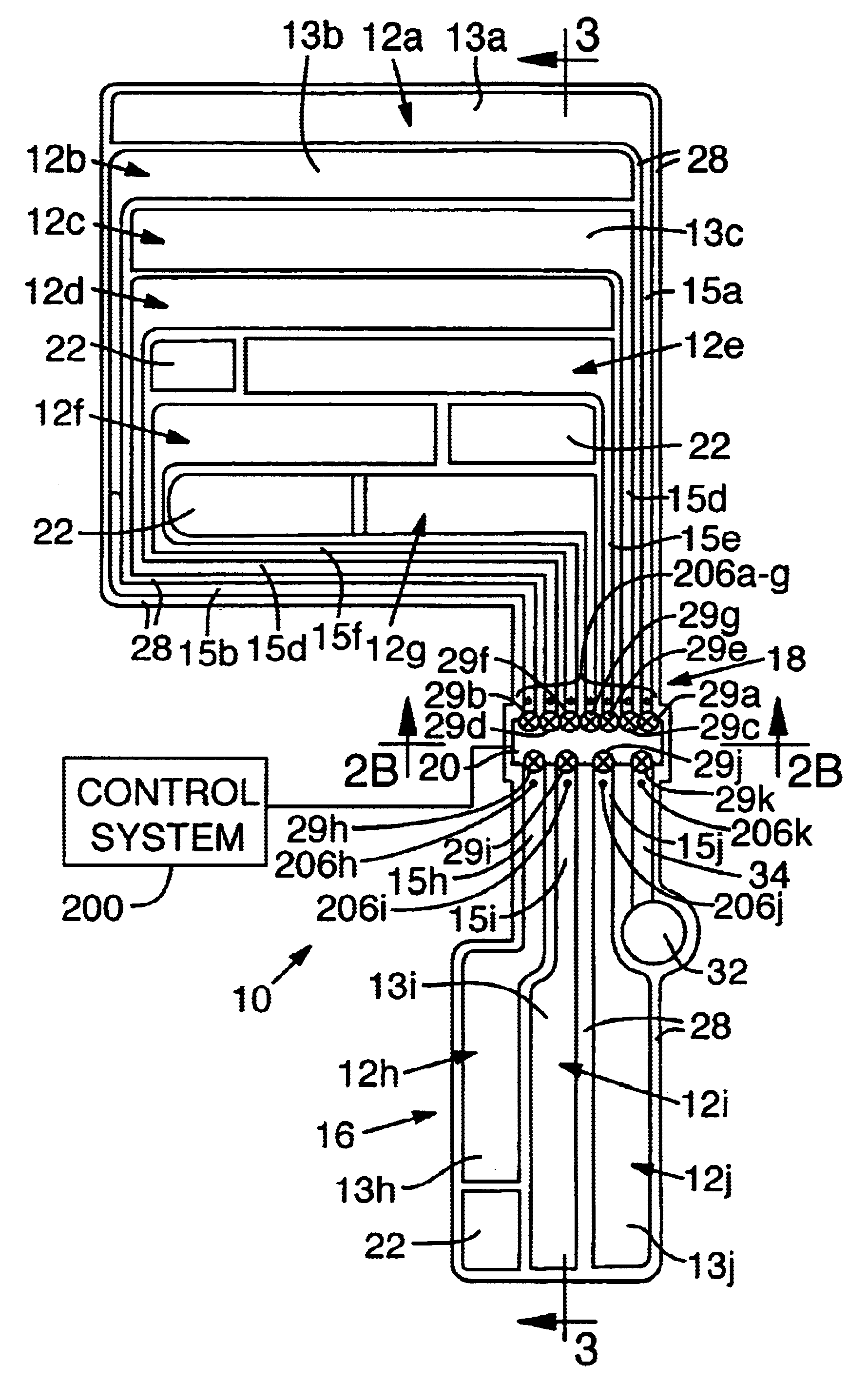
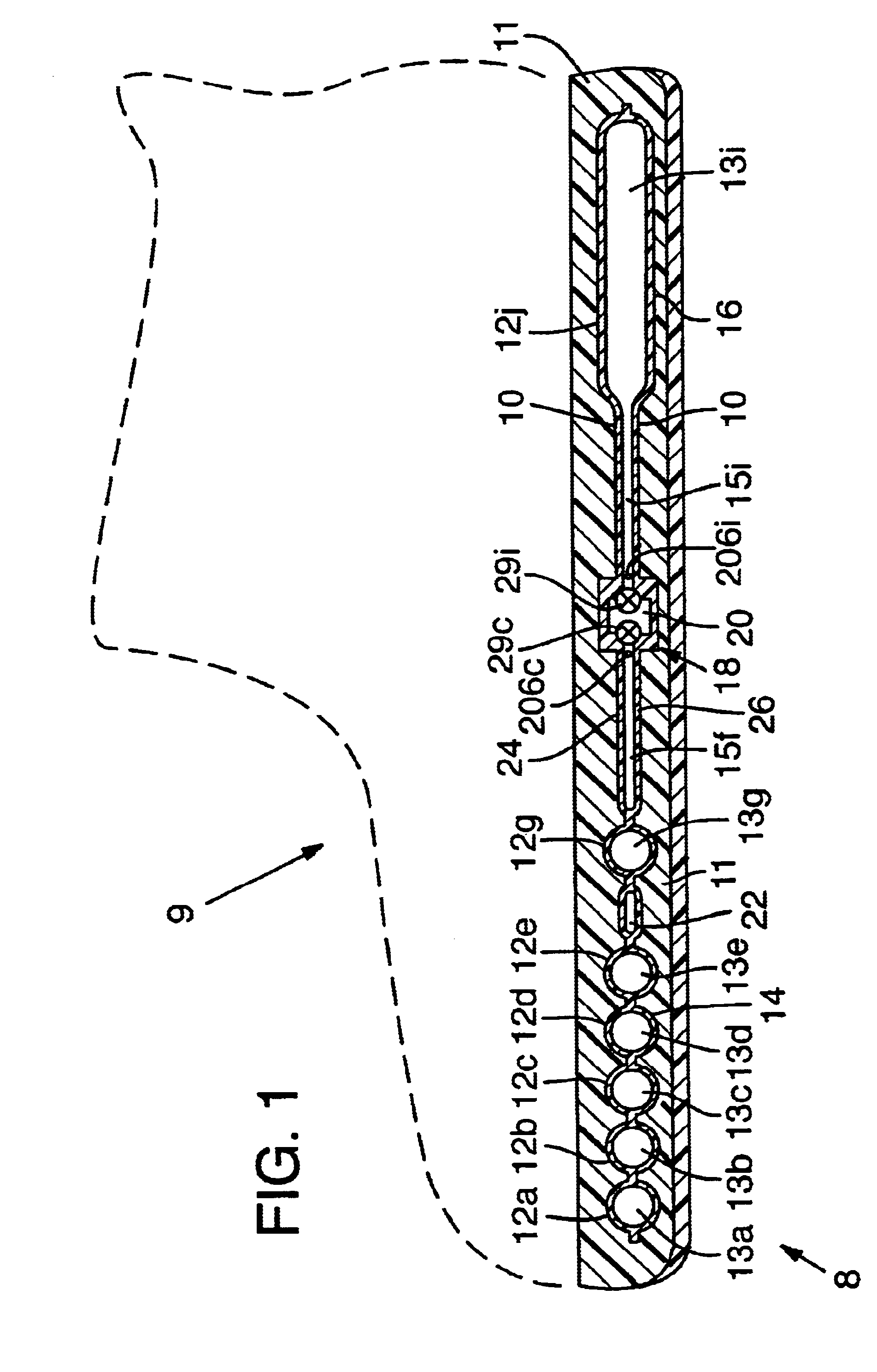
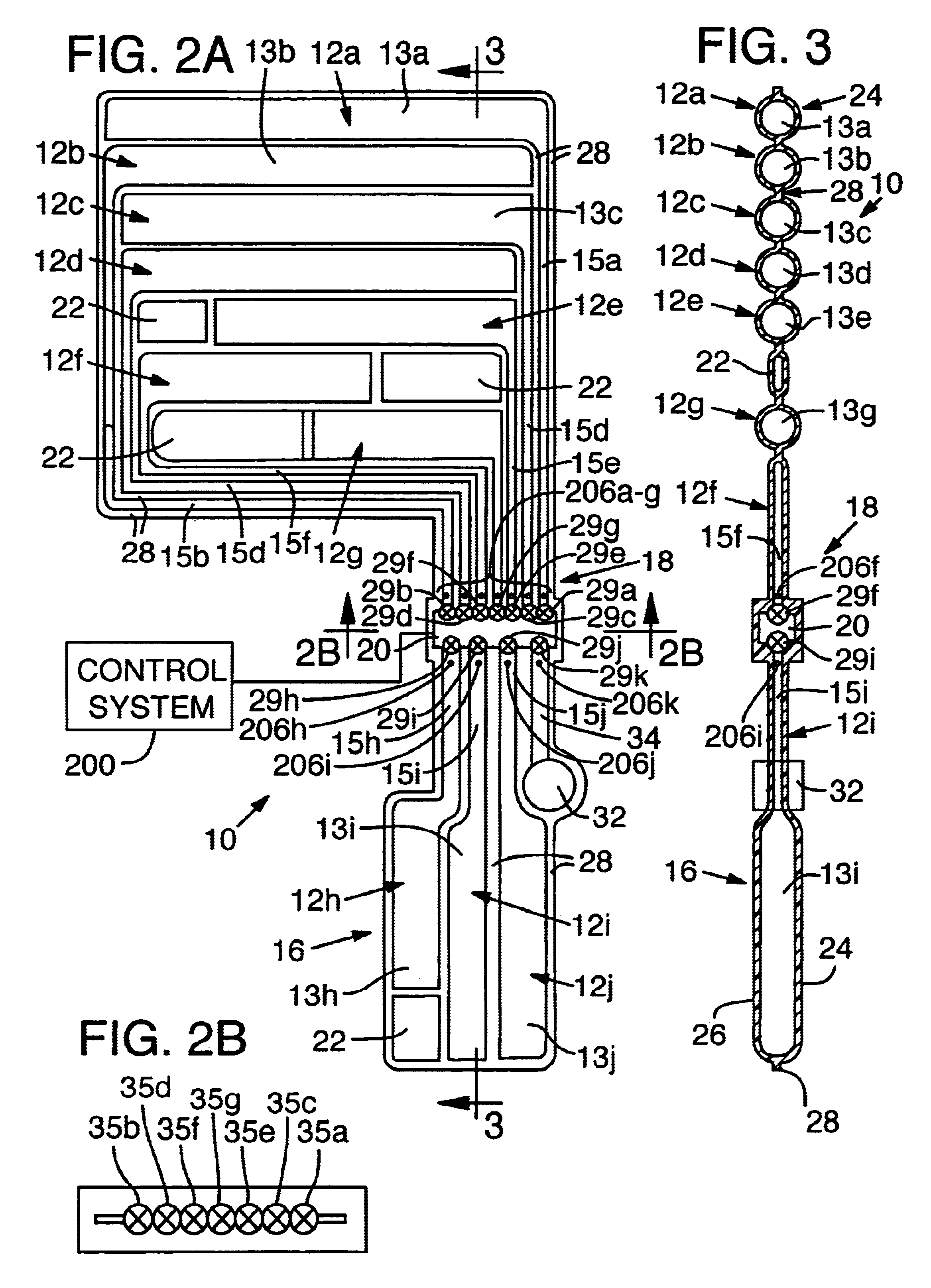
[0032]A cushioning system 8 for use in an article of footwear 9 is disclosed in FIGS. 1 to 9. The cushioning system 8 includes a bladder 10 having a plurality of chambers 12a-j in fluid connection with each other at plenum 20 with each chamber entrance having an individually operable regulator, such as a modulating valve 29. A control system monitors pressure in the chambers and dynamically operates the regulators to change the level of fluid communication between the chambers, thereby changing their respective pressures, to optimize performance of the bladder while the article of footwear is being worn.

A. Bladder Assembly

[0033]In a preferred embodiment of the invention (FIGS. 1-3), a bladder 10 is a thin, elastomeric member defining a plurality of chambers 12 or pockets. The chambers 12 are pressurized to provide a resilient support. Bladder 10 is particularly adapted for use in the midsole of the shoe, but could be included in other parts of the sole or have applicability in other...


PUM


Abstract

An article of footwear with a dynamically-controlled cushioning system is disclosed. The cushioning system includes a sealed, fluid-filled bladder formed with a plurality of separate cushioning chambers, and a control system. The control system, which includes a CPU, pressure sensors and valves, controls fluid communication between the chambers to dynamically adjust the pressure in the cushioning chambers for various conditions such as the activity that the footwear is used in, the weight of the individual and the individual's running style. Certain adjustments can be made while the footwear is in use.

Description

RELATED APPLICATION INFORMATION[0001]This application is a divisional patent application of U.S. patent application Ser. No. 09 / 552,163, entitled “Dynamically-Controlled Cushioning System For An Article Of Footwear,” filed on Apr. 18, 2000 and naming Daniel R. Potter and Allan M. Scbrock as inventors, which application issued as U.S. Pat. No. 6,430,843 B1 on Aug. 13, 2002.FIELD OF THE INVENTION[0002]This invention relates to a cushioning system for an article of footwear. In particular, the cushioning system includes a fluid-filled bladder having separate reservoir chambers. The chambers are in fluid communication with each other, and a control device dynamically-distributes and regulates pressure within the chambers based on sensed and user input criteria.BACKGROUND OF THE INVENTION[0003]Articles of footwear, such as the modern athletic shoes, are highly refined combinations of many elements which have specific functions, all of which work together for the support and protection of...

Claims


Application Information

Patent Timeline
IPC IPC(8): A43B13/18A43B13/20A43B7/32
CPCA43B3/0005A43B13/206A43B13/203A43B3/34A43B13/20A43B3/44
Inventor POTTER, DANIEL R.SCHROCK, ALLAN M.
Owner NIKE INC
Why Eureka
Try Eureka