

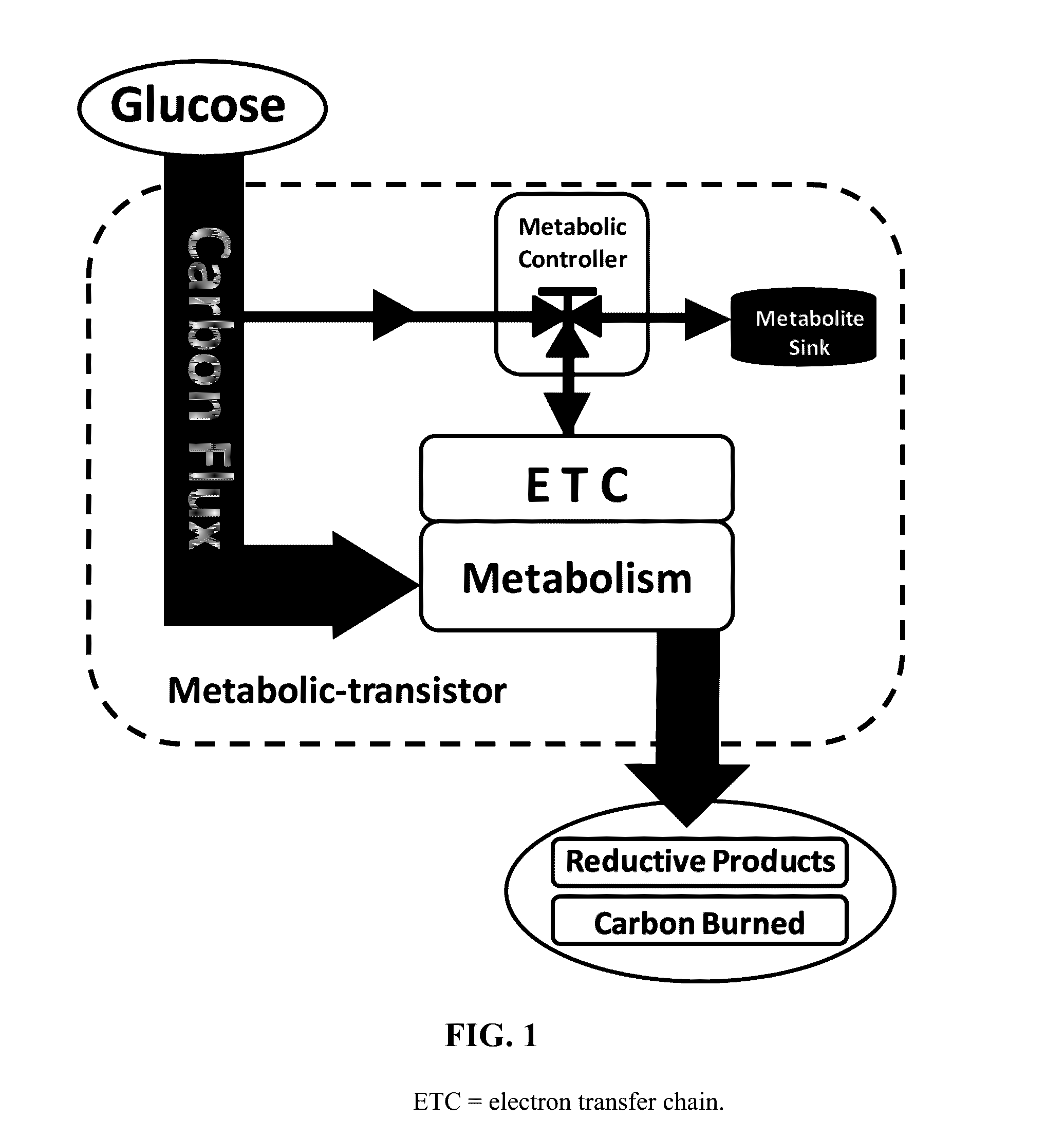
Metabolic transistor in bacteria
- Summary
- Abstract
- Description
- Claims
- Application Information
AI Technical Summary
Benefits of technology
Problems solved by technology
Method used
Image

Examples
Embodiment Construction
[0055]We propose a new strategy based on network topology and indirect control of competitive pathways by introducing additional nodes where flow through the biosynthetic pathway of interest can be controlled by partitioning at these newly introduced nodes. In other words, we introduce a diverting pathway and use this diversion to negatively control the level of a key participant of a competitive pathway, and thus to slow the flux through a competitive pathway and thereby increasing the flux through the pathway of interest.
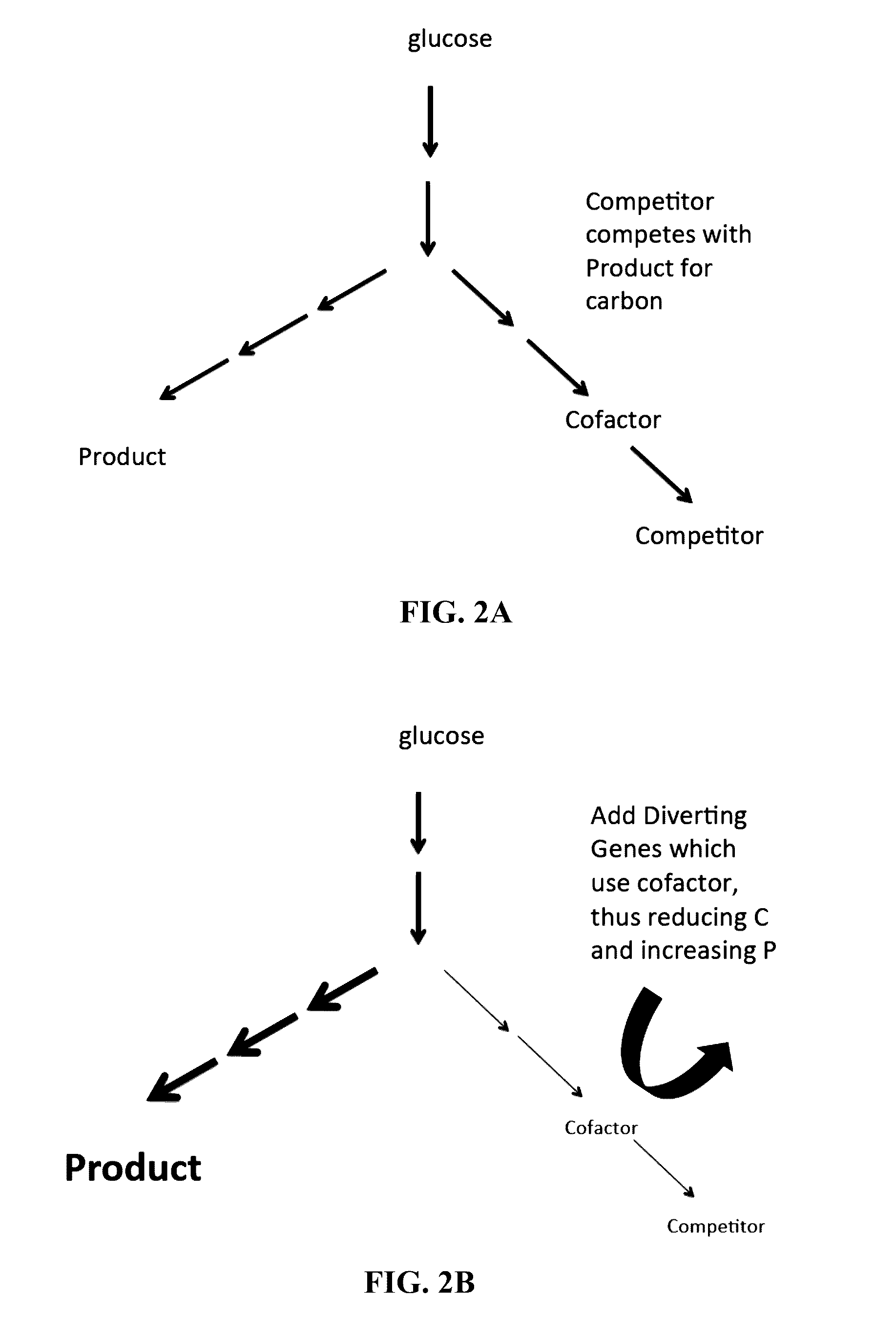
[0056]FIG. 2A shows the desired pathway to product P that competes for carbon flow with the competitive pathway C. Adding diverting genes in FIG. 2B will divert cofactor or key intermediate in pathway C, thus slowing it and instead allowing the carbon flux to flow to P. Ideally, the relative amounts of the enzymes and their Km values need to be within an appropriate range relative to the cofactor or key intermediate. If these factors are within the appropriate ran...
PUM
| Property | Measurement | Unit |
|---|---|---|
| Fraction | aaaaa | aaaaa |
| Molar density | aaaaa | aaaaa |
| Molar density | aaaaa | aaaaa |
Abstract
Description
Claims
Application Information