In-chassis engine compression release brake diagnostic test and electronic control module using the same

a technology of compression release brake and diagnostic test, which is applied in the direction of electric control, machines/engines, instruments, etc., can solve the problems of performance deviations affecting the performance of other engine components, and the performance of the brake can change over tim

Inactive Publication Date: 2005-05-17
CATERPILLAR INC
View PDF9 Cites 16 Cited by
  • Summary
  • Abstract
  • Description
  • Claims
  • Application Information

AI Technical Summary

Benefits of technology

[0008]In another aspect of the present invention, a method of performing an in-chassis engine compression release brake diagnostic test includes providing an engine having an electronic control module and a plurality of cylinders, wherein each of the cylinders includes a fuel injector and an engine compression release brake. At least one of the engine compression release brakes is then tested, in part by operating a first portion of the cylinders in a power mode for a test cycle, operating a second portion of the cylinders in a braking mode for the test cycle and determining at least one of a trial fuel injector response and a trial engine response. The trial fuel injector response is then compared to an expected fuel in

Problems solved by technology

Further, this engine compression release brake performance can change over its useable life, such as after it has been broken in.
In addition to influencing engine operation when ut

Method used


Image

  • In-chassis engine compression release brake diagnostic test and electronic control module using the same
  • In-chassis engine compression release brake diagnostic test and electronic control module using the same
  • In-chassis engine compression release brake diagnostic test and electronic control module using the same

Examples


Embodiment Construction

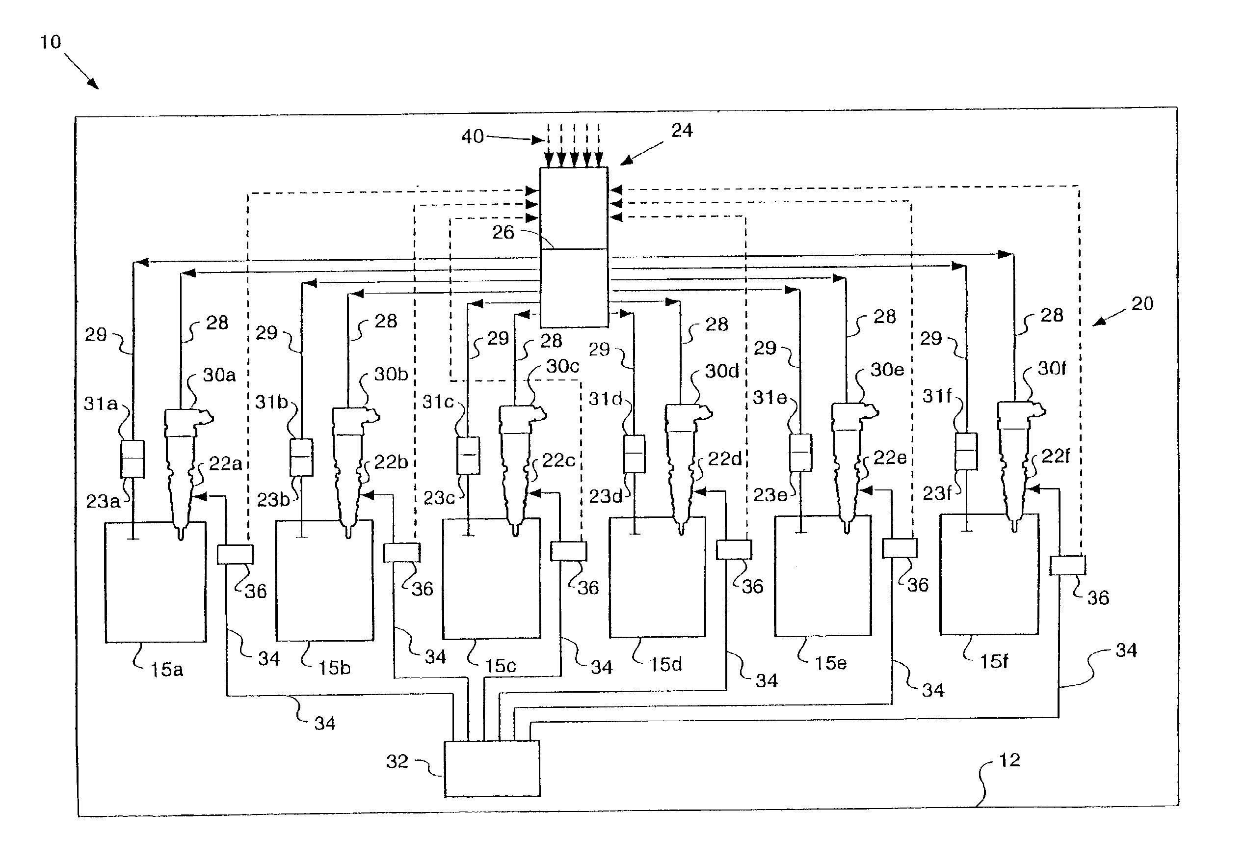
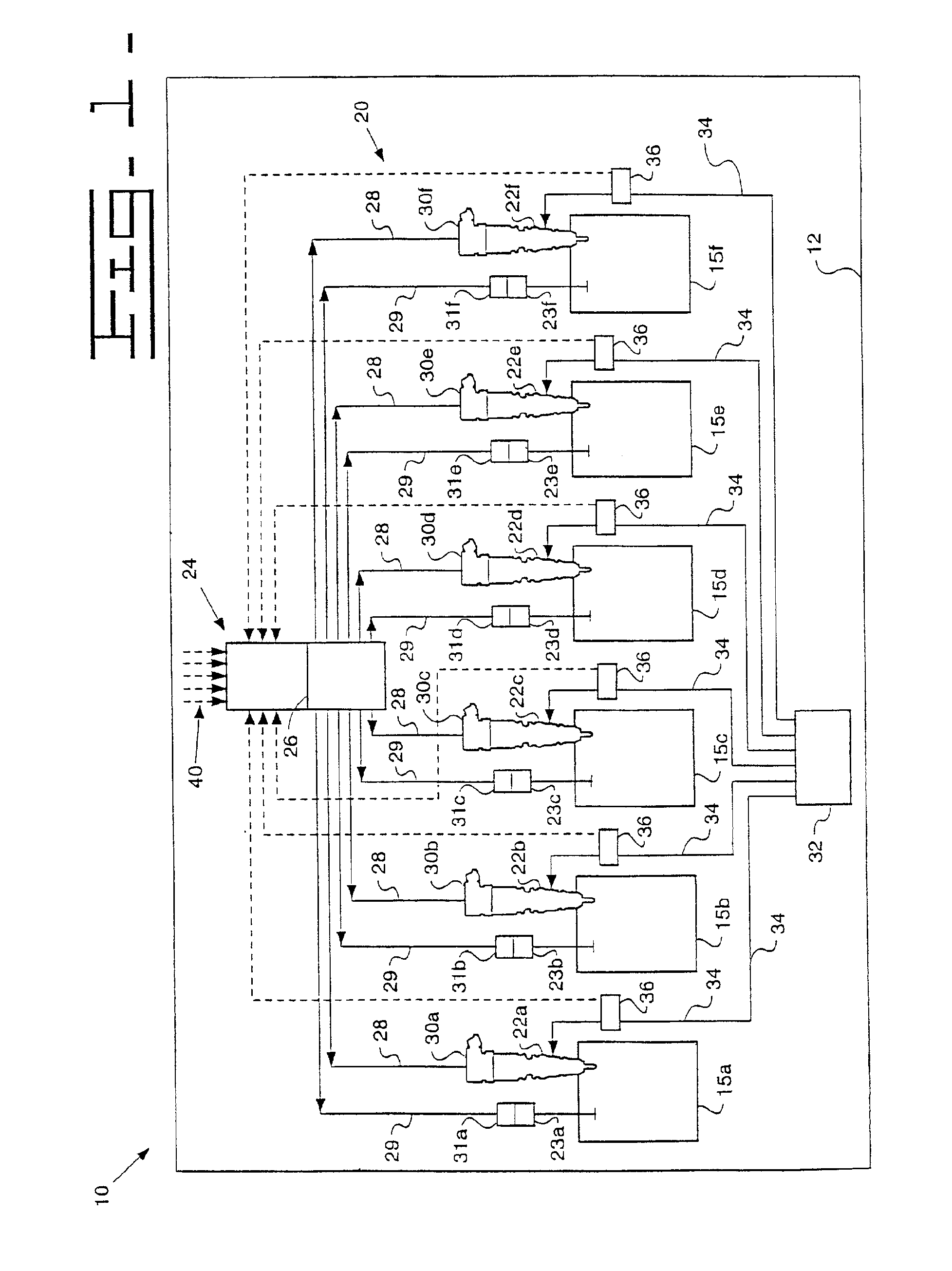
[0021]Referring now to FIG. 1, a schematic diagram of an engine with a direct fuel injection system 20 is shown. The system, generally indicated by reference numeral 20, provides an engine 10 having a plurality of cylinders 15 defined by an engine housing 12, each including a corresponding fuel injector 22 and engine compression release brake 23. In a preferred embodiment, engine 10 is a compression-ignition internal combustion engine; in the illustrated embodiment engine 10 is a six-cylinder diesel engine.

[0022]Fuel injection system 20 has a source of fuel 32 that supplies fuel to fuel injectors 22 by means of fuel supply lines 34 in a manner readily known to those skilled in the art. Fuel injection system 20 preferably has flow sensors 36, attached to fuel supply lines 34, as means for determining fuel consumption. Fuel injection system 20 also provides communication lines 38 that function to communicate the information concerning fuel consumption from flow sensors 36 to electroni...


PUM


Abstract

It is becoming more common for diesel engine cylinders to include an engine compression release brake that can utilize energy built up in the cylinder to provide additional braking for the vehicle. The present invention utilizes a software diagnostic test that is stored in an electronic control module to detect defects in the engine compression release brakes. In particular, the present invention operates a first portion of the engine cylinders in a power mode and a second portion of the engine cylinders in a braking mode and compares a resulting fuel injector response or engine response to an expected value to determine if one or more of the engine compression release brakes are performing as expected.

Description

[0001]This application is a continuation of application Ser. No. 10 / 029,415 Dec. 20, 2001 now abandoned.TECHNICAL FIELD[0002]This invention relates generally to engine compression release brake performance, and more particularly to an in-chassis engine compression release brake diagnostic test and an electronic control module using the same.BACKGROUND[0003]Performance of an actual engine compression release brakes can deviate from performance of a nominal engine compression release brake for a number of reasons, including machining tolerances of engine compression release brake components. This deviance from expected behavior can vary depending upon engine operating condition. For instance, an engine compression release brake might provide more load than expected at a low engine speed but less load than expected at a higher engine speed. Further, this engine compression release brake performance can change over its useable life, such as after it has been broken in.[0004]In addition ...

Claims


Application Information

Patent Timeline
IPC IPC(8): F02D41/22F02D41/32F02D41/36F02D13/04F02B3/00F02B3/06F02D41/00
CPCF02D41/0087F02D41/221F02D13/04F02B3/06F02B2275/14Y02T10/123Y02T10/12
Inventor MARTIN, DAVID E.CORNELL, SEAN O.SHINOGLE, RONALD D.LEMAN, SCOTT A.
Owner CATERPILLAR INC
Why Eureka
Try Eureka