Foot pressure testing structure

a foot pressure and testing structure technology, applied in the field of improved foot pressure testing structure, can solve the problems of long-time practice, pathological changes in our joints, and the assessment of gait requires some techniques, so as to facilitate the medical assessment and production of foot accessories, improve the effect of foot pressure testing structure and improve the quality of li

Inactive Publication Date: 2005-05-17
LO MING JOR
View PDF5 Cites 14 Cited by
  • Summary
  • Abstract
  • Description
  • Claims
  • Application Information

AI Technical Summary

Benefits of technology

[0016]This present invention discloses an improved foot pressure testing structure, which comprises a test memory mold plate, a meshed plate and an evenly distributed convex moldboard being stacked with each other on a sole, such that when a patient wears the foot pressure testing structure and walks several steps (or for several minutes) for a test, the test memory mold plate is pressed due to the weight and pressure produced by the patient and the time accumulated in such walking activity, which causes the bottom of the test memory mold plate to be attached closely to and embedded deeply into the meshed plate and the moldboard to form a concave line. The length, depth, area of distribution, and variation of de...

Problems solved by technology

In general, at least 80% of us have foot problems, and injuries to our ankles or feet change the dynamics of our gait and further produce pressure on the joints of our lower limbs, and thus may cause pathological changes to our joints.
However, the gait assessment requires some techniques and takes a long-time practice as well as having a standardization of the process before a medical professional to develop the necessary assessing skill.
At present, the foot pressure measuring instruments have the following three situations:(1) Since the existing foot pressure measuring instruments are imported, therefore the price is high, and the costs for consuming materials and maintenance are also high.(2) Th...

Method used


Image

  • Foot pressure testing structure
  • Foot pressure testing structure
  • Foot pressure testing structure

Examples


Embodiment Construction

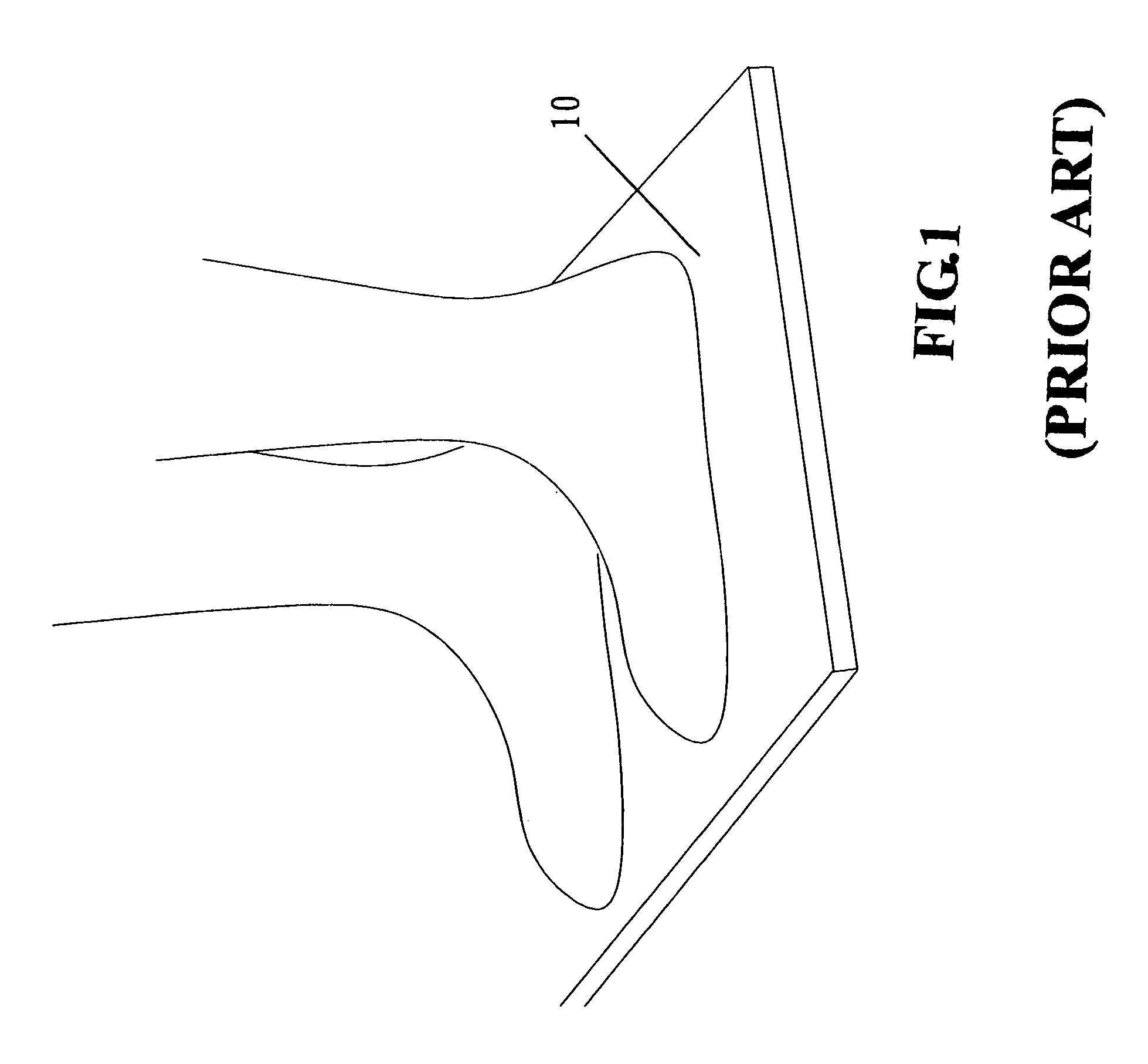
[0025]Please refer to FIG. 1 for an illustrative view of the prior-art foot pressure measuring instrument using a force board for the test. Its method, objectives and shortcomings have been described in the previous section and thus will not be described here.

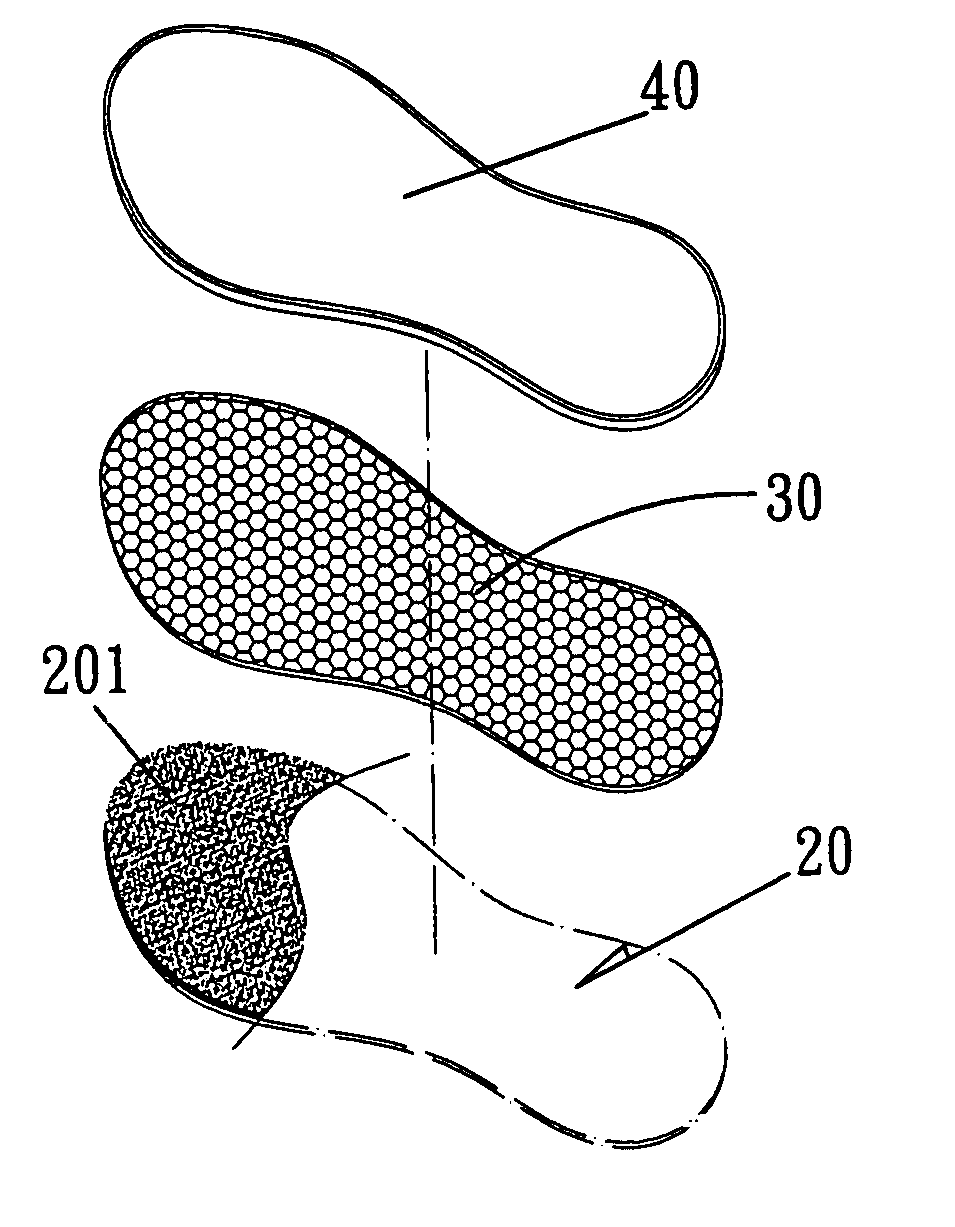
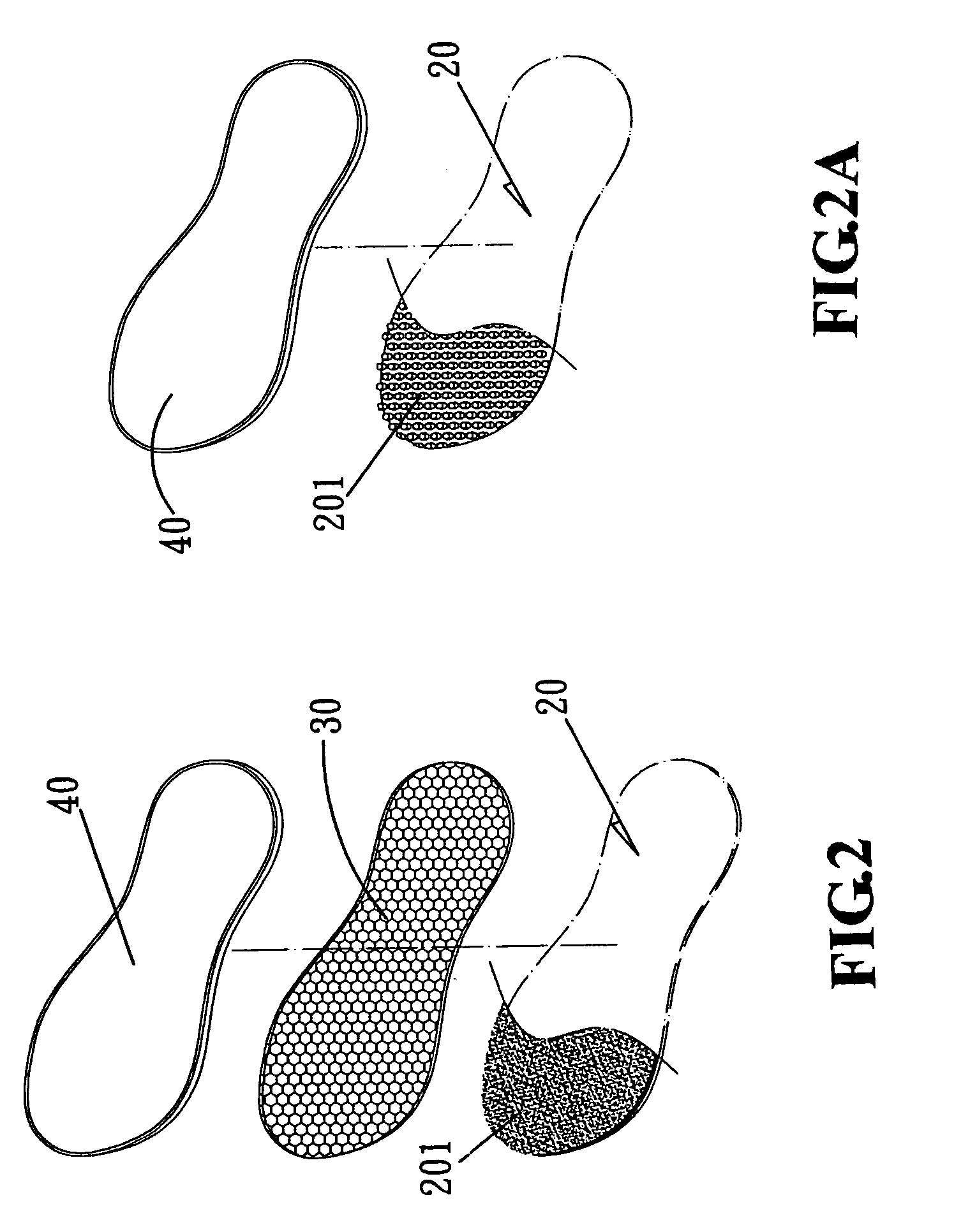
[0026]The present invention discloses an improved foot pressure testing structure, which comprises:[0027]a moldboard 20, being a flexible sole (as shown in FIGS. 2 and 2A) and having a plurality of protrusions 201 thereon, wherein the shape, size, coarseness, and density of distribution of the protrusions 201 vary as needed, and a meshed plate 30 being coupled on top of the moldboard 20; and[0028]a testing memory plate 40, being a foam flexible member made of a memory material in the shape of an insole and having the features of being easily compressed and deformed, durable and permanently fixed into a shape after being deformed;[0029]thereby, the moldboard 20 and the testing memory plate 40 (as shown in FIGS. 2A and 3A) are s...


PUM


Abstract

An improved foot pressure testing structure which comprises a test memory mold plate, a meshed plate and an evenly distributed convex moldboard being stacked with each other on a sole, such that when a patient wears the foot pressure testing structure and walks several steps (or for several minutes) for a test, the test memory mold plate is pressed due to the weight and pressure produced by the patient and the time accumulated in such walking activity, which causes the bottom of the test memory mold plate to be attached closely to and embedded deeply into the meshed plate and the moldboard to form a concave line. The length, depth, area of distribution, and variation of density of the concave line varies with different gaits, and such information can be used as a reference for medical or athletic evaluators to analyze the position and magnitude of the exerted force and the central line of the pressure along a traveling path to facilitate the medical assessment and production of a foot accessory such as a foot base and a pair of shoes. The foot pressure testing structure according to the invention has the features of simple structure, low cost, easy-to-operate, and visually inspecting the result without requiring any other additional measuring instruments.

Description

BACKGROUND OF THE INVENTION[0001]1. Field of the Invention[0002]The present invention relates to an improved foot pressure testing structure, more particularly to an improved foot pressure testing structure that makes use of a footprint mat method to movably mold the magnitude and the central line of a traveling path of the pressure exerted on our feet as a reference for the medical assessment and production of foot accessories such as foot-bases and shoes.[0003]2. Description of the Related Art[0004]Feet play an important role for supporting our body weight, reducing the force exerted on our lower limbs and related joints, absorbing vibrations, buffering impacts and controlling the balance of our body when our body is in contact with the ground. Such functions can be carried out mainly by the coordination of our tissues including bones, ligaments and muscles, etc.[0005]In general, at least 80% of us have foot problems, and injuries to our ankles or feet change the dynamics of our g...

Claims


Application Information

Patent Timeline
IPC IPC(8): A63B5/22A63B5/00A61B5/103A61B5/107
CPCA61B5/1078A61B5/1036
Inventor LO, MING-JOR
Owner LO MING JOR
Why Eureka
Try Eureka