Polymer drilling bead recovery system and related methods

Active Publication Date: 2005-05-17
MI
View PDF43 Cites 28 Cited by
  • Summary
  • Abstract
  • Description
  • Claims
  • Application Information

AI Technical Summary

Benefits of technology

[0011]In still yet another embodiment, the recovery apparatus further comprises a motor control panel. In a further embodiment, the recovery tank further comprises an opening at the top portion of the tank leading to the internal cavity. In a further embodiment, the shaker deck is situated above and / or partially within the internal cavity of the recovery tank. In yet a further embodiment, the apparatus is a low profile device. For purposes of this invention, the term “low profile” is defined as an apparatus that does not require height restrictions to spot the unit. In other prior art recovery systems and designs, the primary shale shaker is mounted several feet above the recovery tank and thus, the unit has tremendous height. The present invention does not require the primary shale shaker to be mounted above the recovery tank and with the transfer vessel; the recovery tank can be placed in a desired location and does not have to be below or in close proximity to the drilling rig shale shaker.
[0016]In still a further embodiment, the pump is connected to the transfer vessel by a third conduit. In still yet a further embodiment, the transfer vessel further comprises a stand for easy mobility of the vessel to various locations.

Problems solved by technology

In other prior art recovery systems and designs, the primary shale shaker is mounted several feet above the recovery tank and thus, the unit has tremendous height.

Method used


Image

  • Polymer drilling bead recovery system and related methods
  • Polymer drilling bead recovery system and related methods
  • Polymer drilling bead recovery system and related methods

Examples


Embodiment Construction

[0028]As required, detailed embodiments of the present invention are disclosed herein; however, it is to be understood that the disclosed embodiments are merely exemplary of the invention that may be embodied in various forms. The figures are not necessary to scale; some features may be exaggerated to show details of particular components. Therefore, specific structural and functional details disclosed herein are not to be interpreted as limiting, but merely as a basis for the claims and as a representative basis for teaching one skilled in the art to variously employ the present invention.

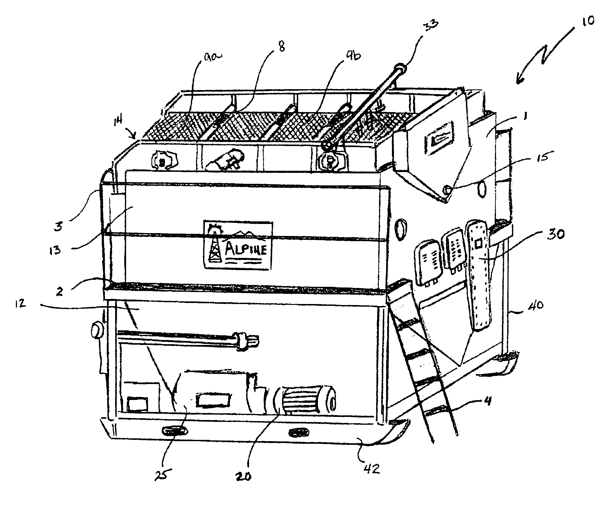
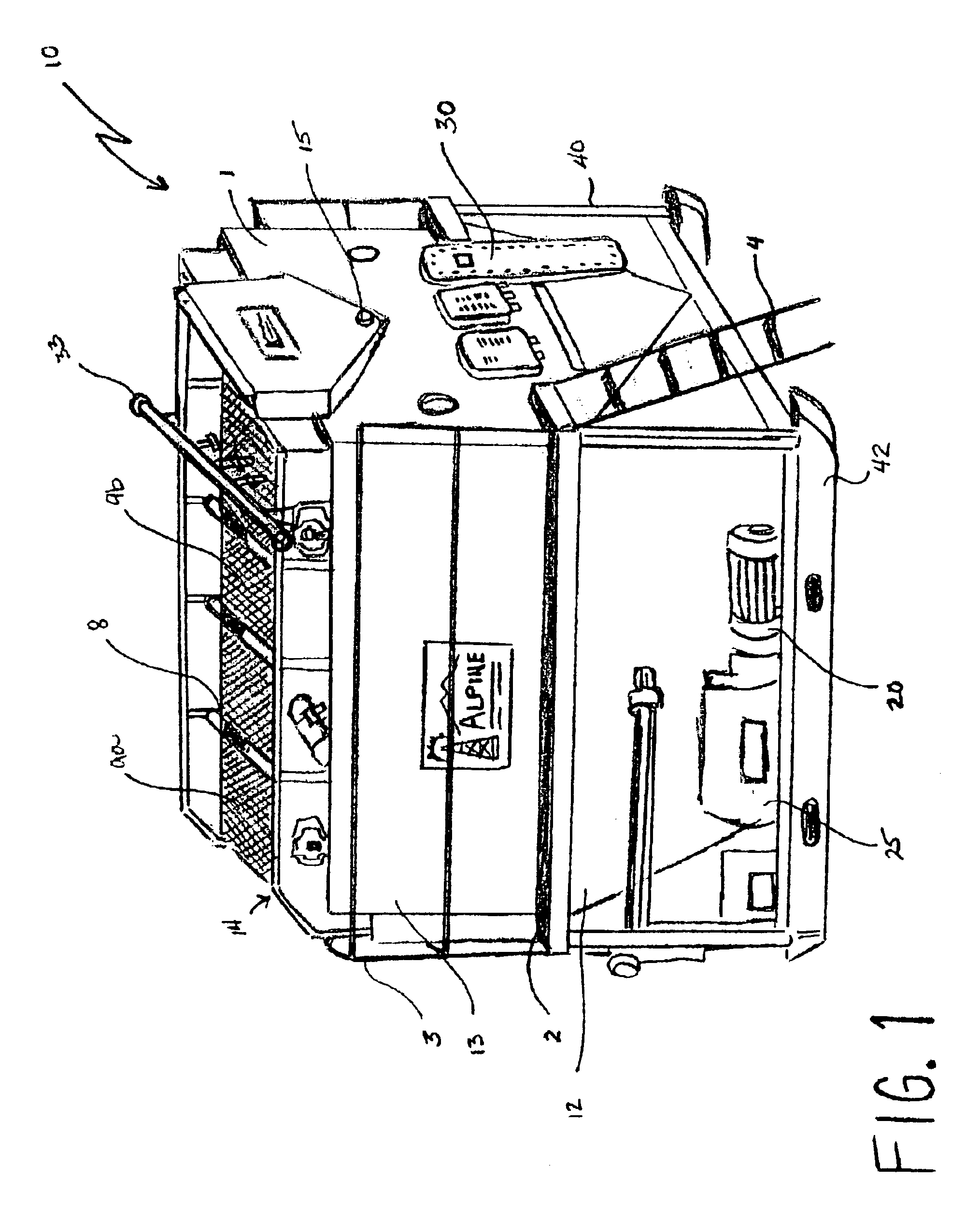
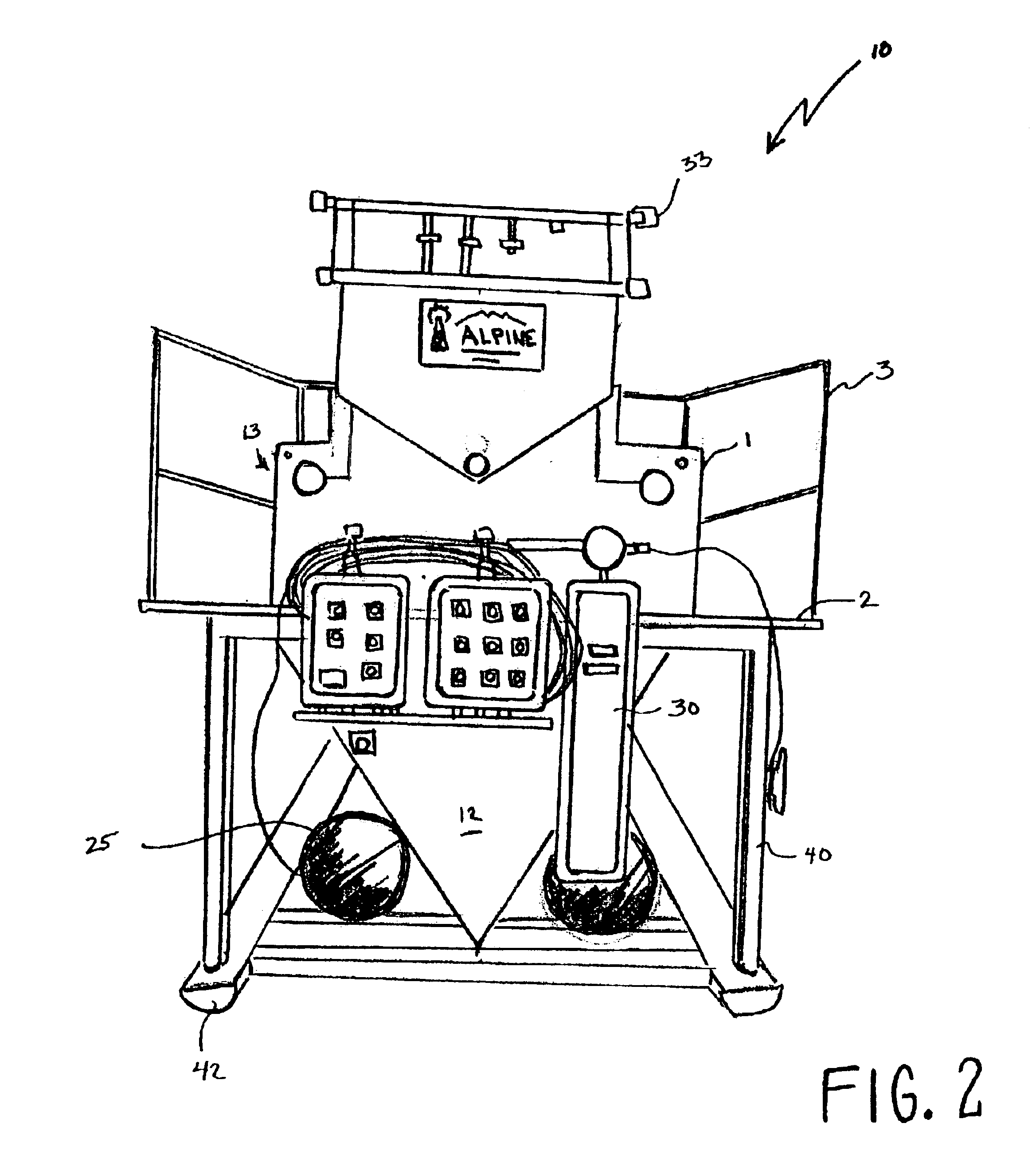
[0029]Referring now to FIGS. 1-2, the present invention provides for a polymer bead recovery apparatus 10 comprising: a housing 1 comprising a recovery tank 12 having an internal cavity (not shown) and an exterior surface 13, the recovery tank 12 having at least one inlet 14 and at least one outlet 15, the recovery apparatus having at least one device 20 for creating a turbulence within the intern...


PUM


Abstract

A polymer bead recovery apparatus is provided comprising: a housing comprising a recovery tank having an internal cavity and an exterior surface, the recovery tank having at least one inlet and at least one outlet, the recovery apparatus having a least one circulation system for creating a force within the internal cavity of the recovery tank, the housing further comprising a walkway situated on the exterior surface of said recovery tank, the recovery tank comprising a shaker deck having a plurality of interchangeable screens and the walkway providing access to said screens, and wherein a mixture of solid particulate material, drilling fluids, polymer beads and drilled solids are separated by a first screen of the shaker deck and the remaining mixture of small materials, fluids and beads enters the recovery tank and are separated by the force created by the circulation system, the undesired small particulate materials are removed from the recovery tank and then separated and isolated by a second screen of the shaker deck and then the polymer beads are isolated and then recovered and collected.

Description

BACKGROUND OF THE INVENTION[0001]1. Field of the Invention[0002]This invention relates to a polymer bead recovery apparatus comprising: a housing comprising a recovery tank having an internal cavity and an exterior surface, the recovery tank having at least one inlet and at least one outlet, the housing further comprising a walkway situated on the exterior surface of the recovery tank, the recovery tank comprising a shaker deck having a plurality of interchangeable screens and being situated above the internal cavity of the recovery tank, and the walkway providing access to the screens, and the recovery tank having a collection vessel under or situated adjacent to the rig shaker screens. More specifically, the present invention relates to a method of recovering polymer beads using a low profile recovery apparatus having an internal cavity, interchangeable screens situated above the cavity, a collection vessel and a circulating system for creating turbulence within the cavity and iso...

Claims


Application Information

Patent Timeline
IPC IPC(8): B03B5/34B03B9/00B03B5/04B03B5/00B03B5/28B07B1/28B07B1/46E21B21/06E21B21/00
CPCB03B5/04B03B5/34B03B9/00B07B1/28E21B21/065B07B1/4672B07B1/46B07B2201/04B07B2230/01
Inventor RAYBORN, JERRY
Owner MI
Why Eureka
Try Eureka