Roll-up truck cover assembly

Inactive Publication Date: 2005-05-17
CHABOT JOHN P
View PDF13 Cites 22 Cited by
  • Summary
  • Abstract
  • Description
  • Claims
  • Application Information

AI Technical Summary

Benefits of technology

[0009]Means are provided for pivotally moving the swinging arms along each of the opposite side walls of the truck body. The swinging arms move in an arch-like manner from one to the other opposite end of truck body. The take-up roll and top cover travel along with the swinging arms and the cover is unwound from the take-up roll in one direction covering the open end of the truck body and

Problems solved by technology

The problem with roll-up truck cover assemblies of the above type is that in order to dispense the cover from the take-up roll over the entire length of the top opening of the truck body and then to move the cover in an opposite direction, it is necessary to rotate the swinging arms in an arch-like fashion to a m

Method used


Image

  • Roll-up truck cover assembly
  • Roll-up truck cover assembly
  • Roll-up truck cover assembly

Examples


Example

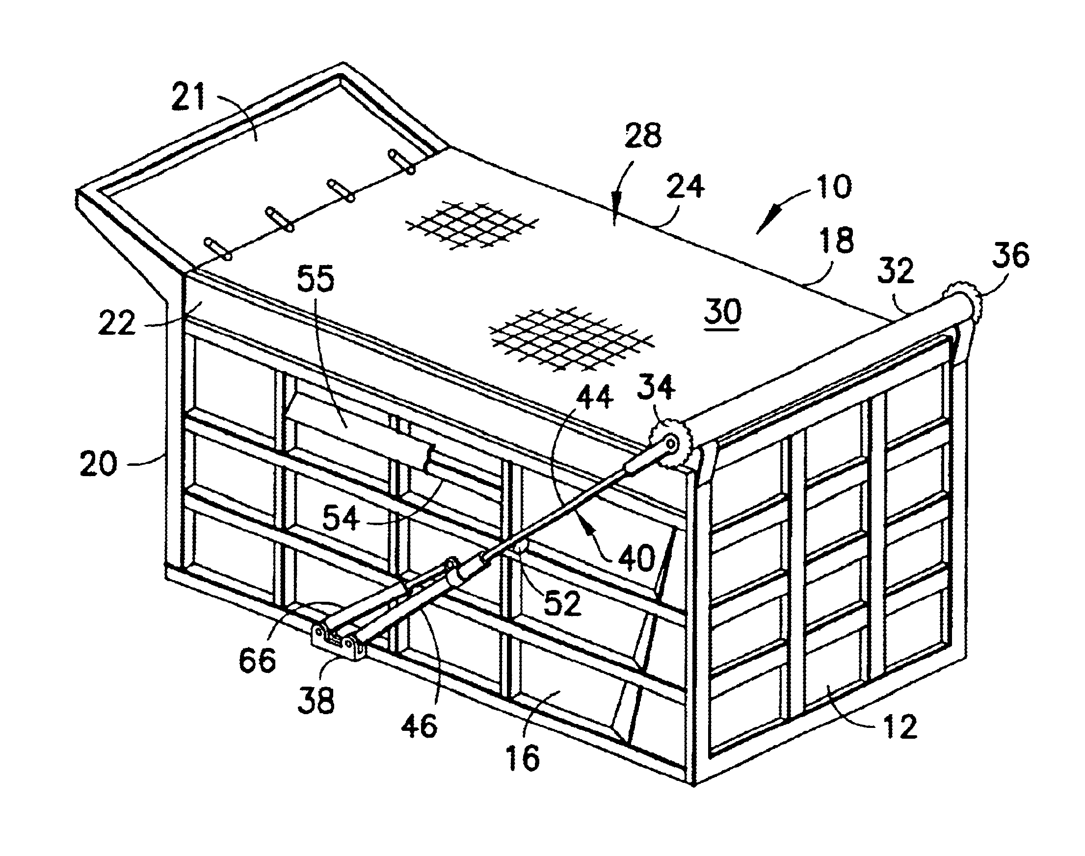
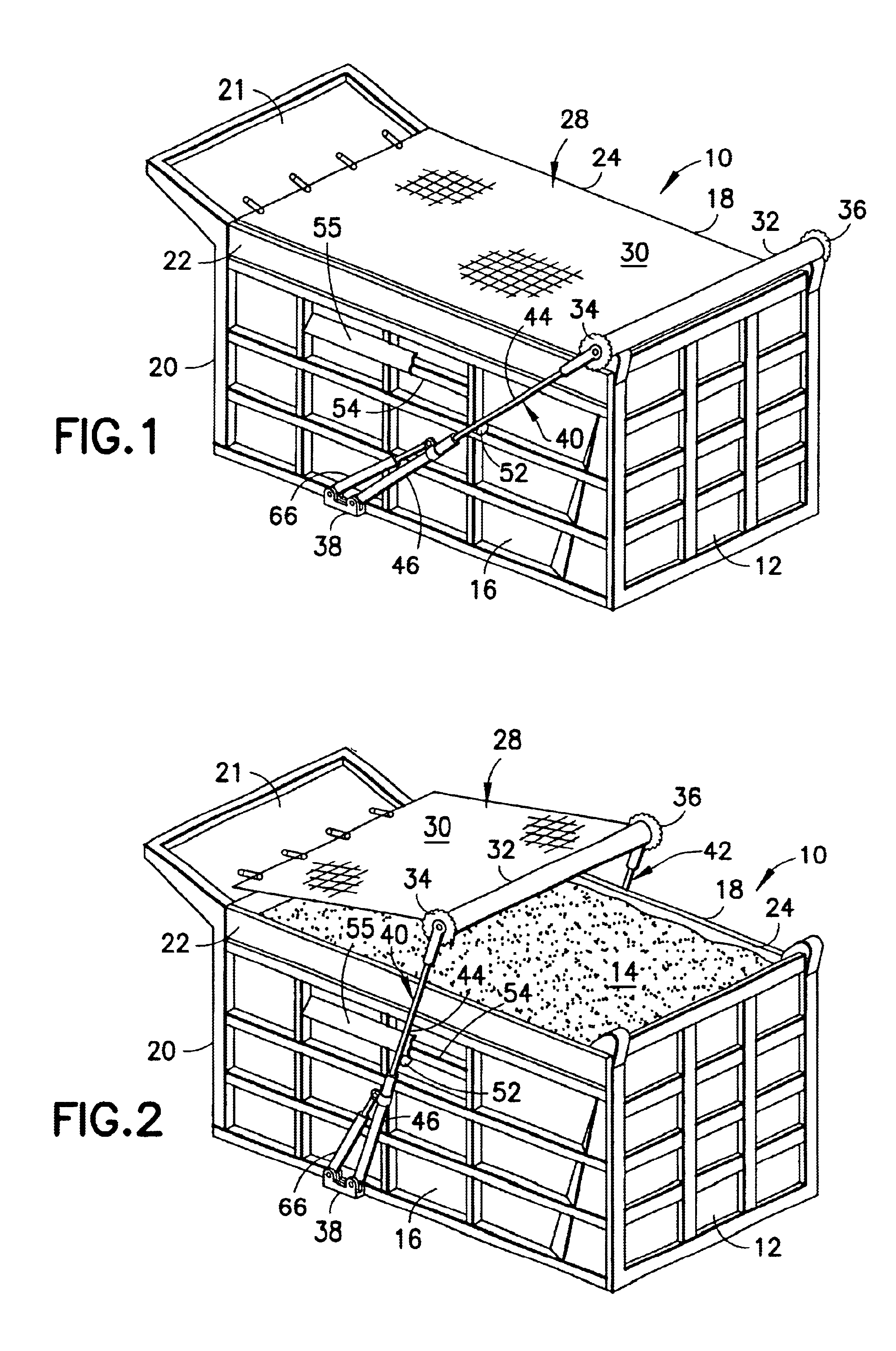
[0024]Referring particularly to FIGS. 1 and 2 of the drawing, there is shown a conventional truck body indicated generally at 10, the cab portion and truck under-carriage including the wheels being omitted for the purposes of simplicity, these portions of the truck assembly actually forming no essential part of the invention. The truck is of the dump variety including a rear-end wall or hinged gate 12 which may be opened in a conventional manner to release the load 14, which may be sand, gravel or dirt fill, for example. The truck body 10 further includes left and right-hand side walls 16, 18 as seen in FIGS. 1 and 2 and in FIG. 6, respectively, and a front wall 20. The side walls are formed with plank-like wood upper sections 22, 24, respectively, which help to retain the load in place. The front wall 20 has an upper or forwardly extending portion forming a conventional headboard 21 which extends substantially above the side walls 16, 18 and the cab portion of the truck (not shown)...


PUM


Abstract

An improved roll-up truck cover assembly is provided for use on trucks having a rectangular open truck body carrying gravel, loose dirt and the like. The roll-up truck cover assembly comprises a rectangular flexible top cover attached at one end to the front wall of the truck body and at the other end to a take-up roll including a biasing member tending to rotate the roll in a take-up operation. A pair of elongated swinging arms are provided one on each opposite side wall of the truck body. The swinging arms may comprise, for example, a first or upper elongated tube or rod rotatably connected at one end to the take-up roll. The first or upper elongated tube or rod is telescopically and retractably mounted at its other end within a second or lower larger diameter tube pivotally mounted to a lower end portion of one of the side walls of the truck body. A roller and an elongated roller guide track are provided for each swinging arm on each opposite side wall of the truck body. Each roller is rotatably mounted onto a shaft which is attached to the first or upper tube of each swinging arm and are moveably engaged within each of the guide tracks. Means are provided for pivotally moving the swinging arms along the opposite side walls of the truck body in an arch-like manner from one to the other opposite end of the truck. The take-up roll and top cover travel along with the swinging arms and the cover is unwound from the take-up roll in one direction covering the open end of the truck body and then wound onto the take-up roll in the opposite direction during the take-up operation. The rollers move along the guide tracks in a straight longitudinal path causing the first or upper tube or rod to retract within the second or lower tube, keeping to a minimum the height to which the take-up roll and top cover can be raised above the truck body.

Description

PRIORITIES[0001]This application claims priority to my provisional application Serial No. 60 / 419,796, filed on Oct. 21, 2002.BACKGROUND OF THE INVENTION[0002]This invention relates to an improved roll-up truck cover assembly of the type wherein a flexible cover is secured at one end of a take-up roll mounted to a pair of swinging arms, one on each side of the truck body, for moving the cover from an open to a closed position over the top opening of the truck to cover a material load, such as gravel or loose dirt. The cover assembly is further adapted to move the cover in an opposite direction to an open position when the load is to be removed. Typically, the swinging arms are made up of two pipes clamped and bolted together to form a one arm unit on each side of the roll-up cover assembly to extend the cover completely over the load from one to an opposite end of truck body. The swinging arms are driven or swung by hydraulic or fluid operated cylinders.[0003]Roll-up cover assemblies...

Claims


Application Information

Patent Timeline
IPC IPC(8): B60J7/08
CPCB60J7/085
Inventor CHABOT, JOHN P.
Owner CHABOT JOHN P
Why Eureka
Try Eureka