Stepper

Inactive Publication Date: 2005-05-17
P & F BROTHER INDAL
View PDF4 Cites 79 Cited by
  • Summary
  • Abstract
  • Description
  • Claims
  • Application Information

AI Technical Summary

Benefits of technology

[0008]The main objective of the present invention is to provide an

Problems solved by technology

Consequently, the manuf

Method used


Image

  • Stepper
  • Stepper
  • Stepper

Examples


Example

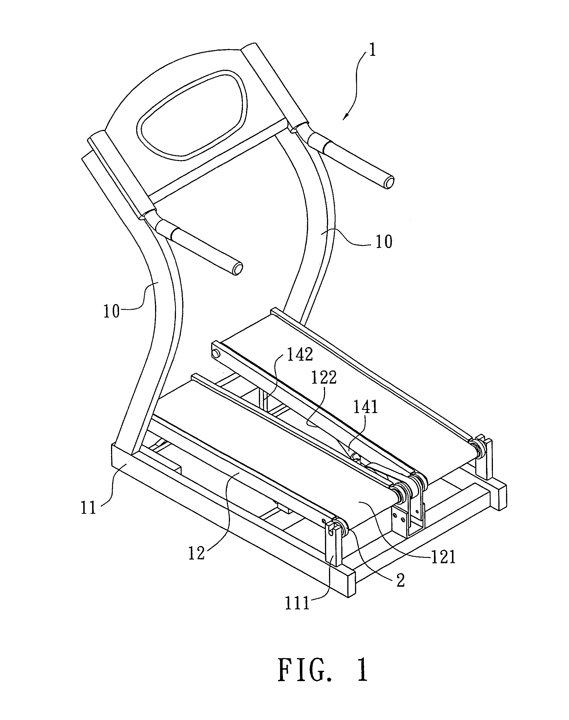
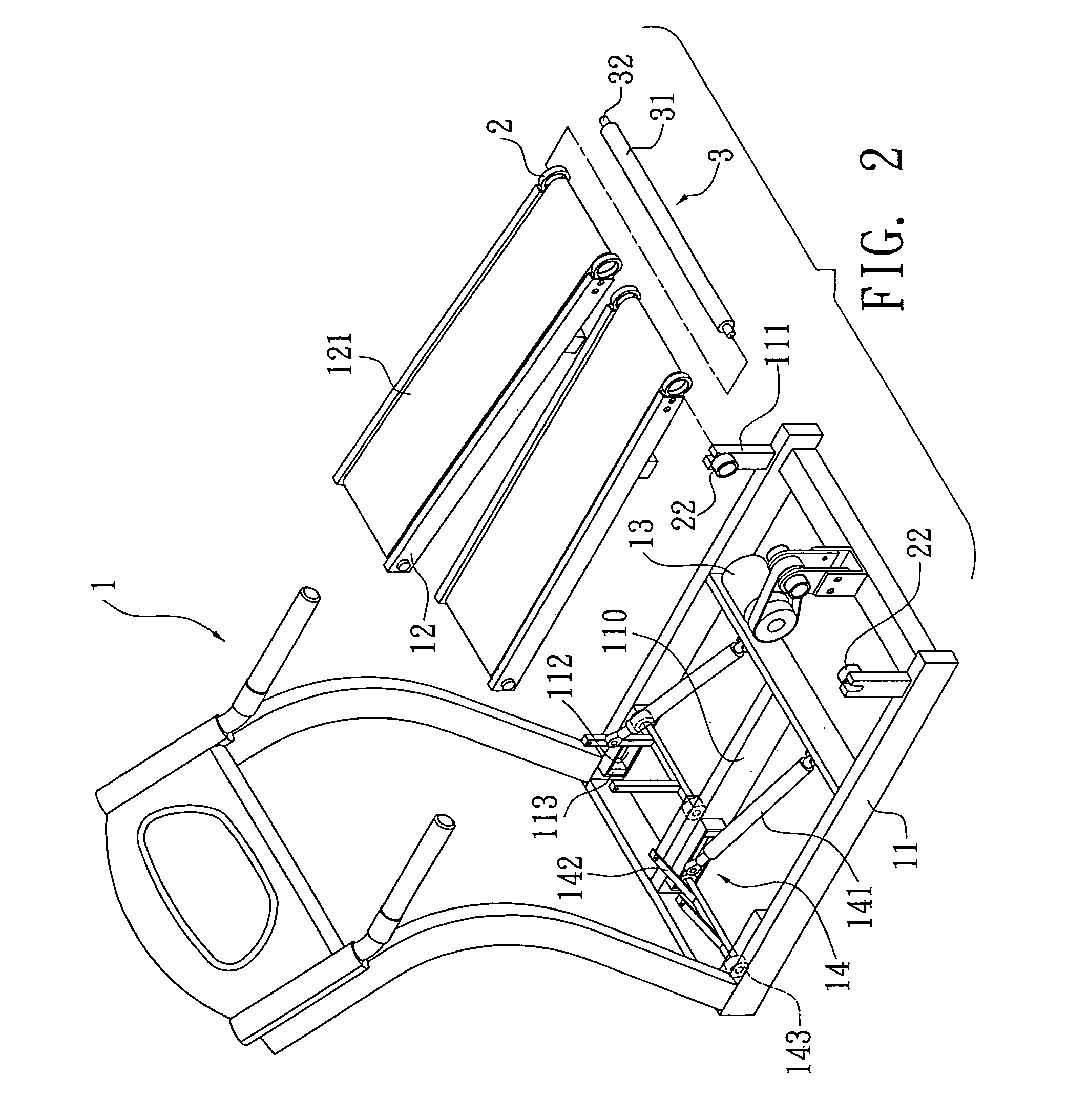
[0017]Referring to the drawings and initially to FIGS. 1–3, a stepper in accordance with the present invention comprises a main frame (1) including a base (11) and two stands (10) respectively upwardly extending from tow opposite sides of a front portion of the base (11). Two swing arms (12) are respectively pivotally mounted to a rear portion of the base (11) due to a pivot structure (2) mounted therein.

[0018]The base (11) has two side rods (not numbered) parallel to each other and two lateral rods (not numbered) respectively connected a front end of each of the two side rods and the middle portion of each of the two side rods. A partition (110) has two opposite ends respectively secured on the two lateral rods to equally divided the base (11) into two portions each corresponding to a corresponding one of the two swing arms (12). The inner side of each of the two side rods and two opposite sides of the partition (110) each has a rectangular casing (112) laterally longitudinally se...


PUM


Abstract

A stepper includes a base and two stands upwardly extending from a front portion of the base. Two swing arms are respectively pivotally connected to a rear portion of the base due to a pivot structure that is mounted in a corresponding one of the two swing arms. Each swing arm has an endless strap sleeved thereon for user to step thereon. A drive shaft pivotally extends through the pivot structures for driving the straps and supporting the two swing arms. A motor is mounted on the base for driving the drive shaft. A restitution structure is mounted under a corresponding one of the two swing arms for providing a restitution force to the corresponding swing arm after being downward stepped.

Description

BACKGROUND OF THE INVENTION[0001]1. Field of the Invention[0002]The present invention relates to stepper, and more particularly to a stepper that includes two endless straps respectively mounted on to two swing arms of the stepper.[0003]2. Description of Related Art[0004]A conventional stepper in accordance with the prior art shown in FIG. 5 comprises a main frame (61) including a base (611) adapted to abut a supporting surface, two stands (612) respectively upwardly extending from two opposite sides of a front portion of the base (611) and a hand post (613) mounted on a free end of each of the two stands (612). Two swing arms (62) are pivotally mounted to a rear portion of the base (611). The two swing arms (62) are parallel to each other and swung opposite to each other. Each swing arm (62) has a rear end pivotally mounted to the rear portion of the base (611) and a front end having an air spring (63) mounted thereon. The air spring (63) has a first end pivotally connected to the ...

Claims


Application Information

Patent Timeline
IPC IPC(8): A63B22/00A63B22/02A63B22/16
CPCA63B22/0056A63B22/02A63B22/0664A63B22/0235A63B2022/067A63B2022/0292A63B22/0292
Inventor CHANG, CHIH YUANWANG, JIAN SEN
Owner P & F BROTHER INDAL
Why Eureka
Try Eureka