Method and apparatus for providing an expandable spinal fusion cage

a spinal fusion cage and expandable technology, applied in the field of implantable fusion cages, can solve the problems of all standard approaches, neural injury, nerve damage and potential neurologic deficit,

Inactive Publication Date: 2005-05-17
RGT UNIV OF CALIFORNIA
View PDF9 Cites 351 Cited by
  • Summary
  • Abstract
  • Description
  • Claims
  • Application Information

AI Technical Summary

Benefits of technology

[0016]The invention is an apparatus for performing spinal fusions comprising two opposing end plates; and at least two opposing collapsible legs disposed between the two opposing end plates. The two opposing end plates and at least two opposing collapsible legs are adapted to be arranged and configured into an expanded cage from a collapsed configuration. The expanded cage assumes a predetermi

Problems solved by technology

There are problems with all of the standard approaches.
If the retraction is not done properly, the procedure could cause neural injury, i.e., nerve damage and potential neurologic deficit.
Violation of the great vessels has a high mortality rate.
The device disclosed in the Larsen reference has several problems.
One problem is that, because the width of the implant is adjusted prior to insertion, a wide insertion slot is necessary despite the reduced profile presented by the collapsed implant.
Another problem is that at least part of the linkage mechanism extends beyond the upper and lower plate portions, thus requiring more invasion into the body cavity to position the implant.
Yet another problem is that the linkage mechanisms must be locked into the expand

Method used


Image

  • Method and apparatus for providing an expandable spinal fusion cage
  • Method and apparatus for providing an expandable spinal fusion cage
  • Method and apparatus for providing an expandable spinal fusion cage

Examples


Embodiment Construction

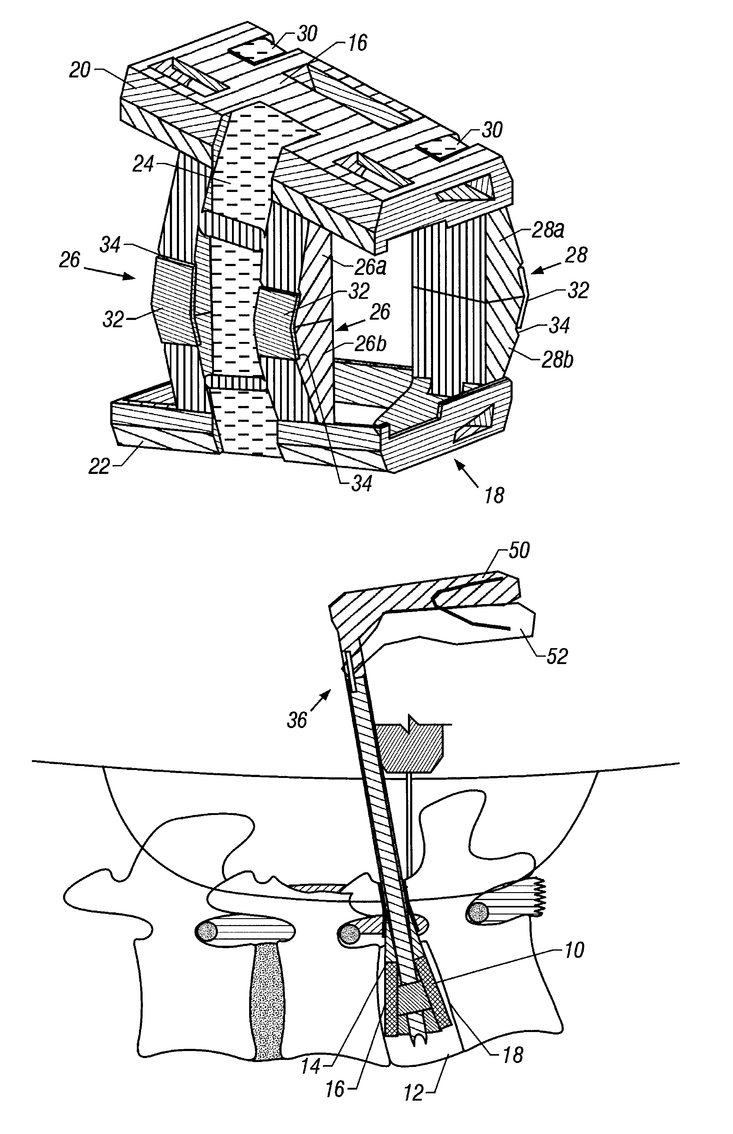
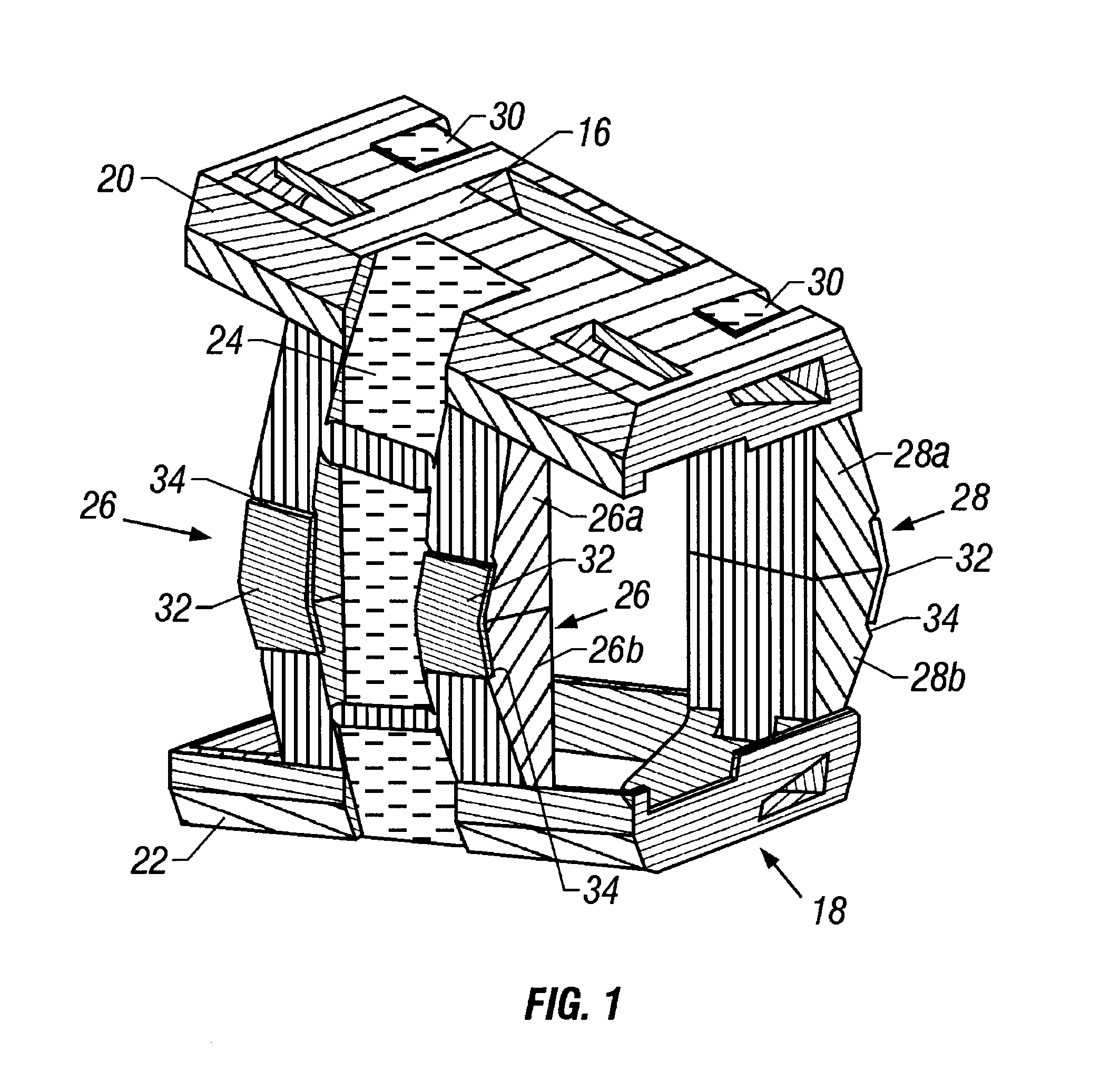
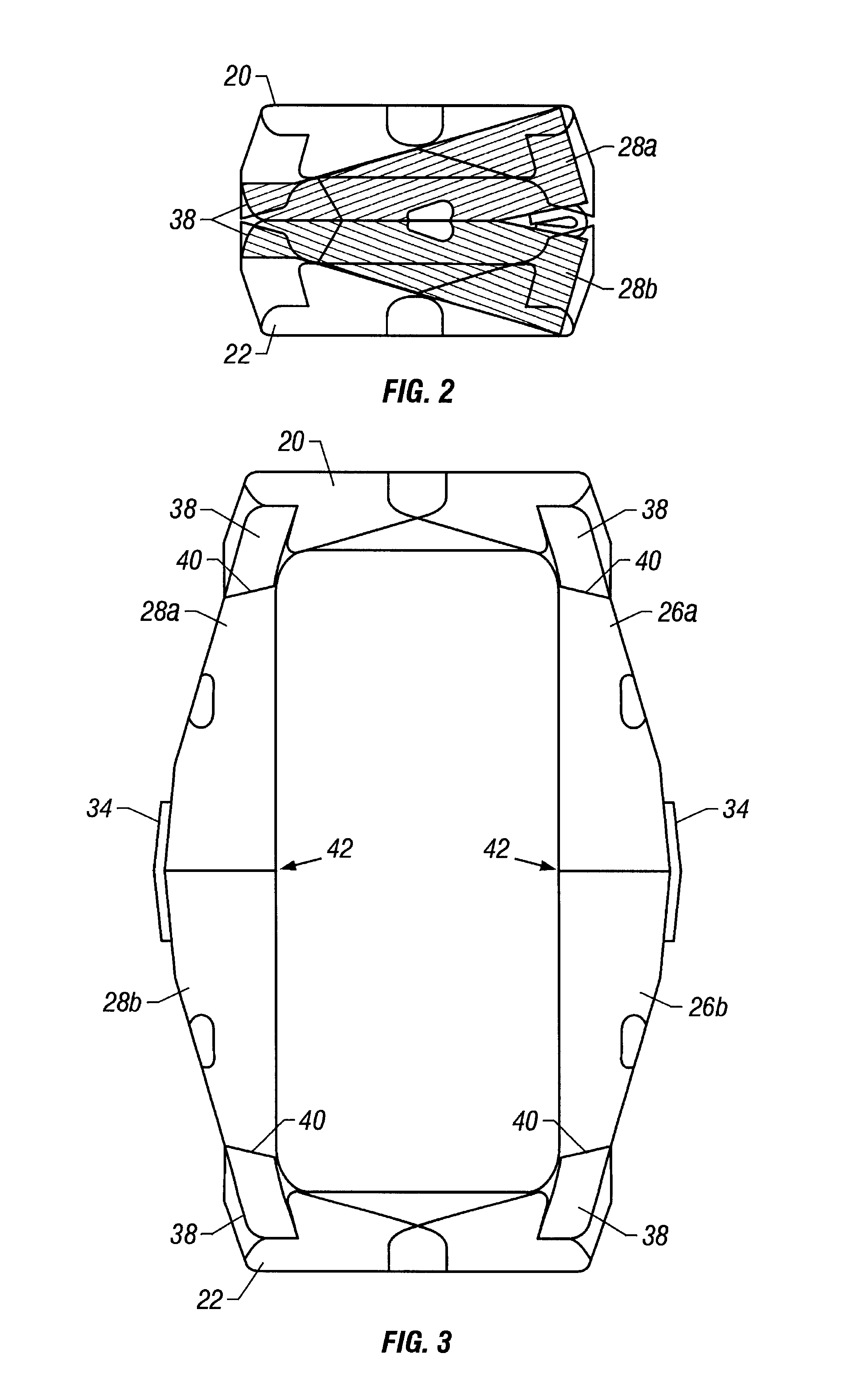
[0045]The spinal fusion cage of the invention comprises two opposing end plates, and three opposing collapsible legs. The two opposing end plates and three opposing collapsible legs are adapted to be configured into an expanded cage from a collapsed configuration. The expanded cage assumes a predetermined rigid shape and volume for disposition between two adjacent vertebrae. The collapsed configuration of the cage is adapted for posterior insertion into the disk space. The apparatus further comprises locking means for permanently or at least temporarily locking the legs and maintaining the cage in an expanded configuration. One of the legs is medially disposed on a first side of the cage and the other two are laterally disposed with respect to the end plates on a second side. The three legs have differing lengths so that the cage assumes a wedge-shaped envelope in the expanded configuration. The wedge-shaped envelope reestablishes a predetermined lordosis between fused vertebrae. Th...


PUM


Abstract

The spinal fusion cage of the invention comprises two opposing end plates, and three opposing collapsible legs. The two opposing end plates and three opposing collapsible legs are adapted to be configured into an expanded cage from a collapsed configuration. The expanded cage assumes a predetermined rigid shape and volume for disposition between two adjacent vertebrae. The collapsed configuration of the cage is adapted for posterior insertion into the disk space. The apparatus further comprises locking means for at least temporarily locking the legs and maintaining the cage in an expanded configuration. One of the legs is medially disposed on a first side of the cage and the other two are laterally disposed with respect to the end plates on a second side. The three legs have differing lengths so that the cage assumes a wedge-shaped envelope in the expanded configuration. The wedge-shaped envelope reestablishes a predetermined lordosis between fused vertebrae. The invention includes an inserter comprised of a tubular member and holding clamp disposed on the distal end of the tubular member. The holding clamp holds the cage in the collapsed configuration for insertion into a confined surgical theater. The cage is then reconfigured to the expanded configuration using the inserter. Further activation of the inserter causes the cage to be temporarily locked into the expanded configuration.

Description

BACKGROUND OF THE INVENTION[0001]1. Field of the Invention[0002]The invention relates to the field of implantable fusion cages for use in the spinal column.[0003]2. Description of the Prior Art[0004]Fusion cages provide a space for inserting a bone graft between adjacent portions of bone. In time, the bone and bone graft grow together through or around the fusion cage to fuse the graft and the bone solidly together. One current use of fusion cages is to treat a variety of spinal disorders, including degenerative disc diseases, Grade I or II spondylolistheses, adult coliosis and other disorders of the lumbar spine. Spinal fusion cages (included in the general term, “fusion cages”) are inserted into the intervertebral disc space between two vertebrae for fusing them together. They distract (or expand) a collapsed disc space between two vertebrae to stabilize the vertebrae by preventing them from moving relative to each other.[0005]The typical fusion cage is cylindrical, hollow, and th...

Claims


Application Information

Patent Timeline
IPC IPC(8): A61F2/30A61F2/44A61F2/46A61F2/00
CPCA61F2/447A61F2/4611A61F2310/00023A61F2002/30266A61F2002/30464A61F2002/30471A61F2002/30476A61F2002/30505A61F2002/3055A61F2002/30551A61F2002/30601A61F2002/4475A61F2002/4623A61F2002/4627A61F2002/4635A61F2220/0025A61F2220/0075A61F2220/0091A61F2230/0082A61F2/4603A61F2002/30462A61F2002/30593
Inventor KIESTER, P. DOUGLAS
Owner RGT UNIV OF CALIFORNIA
Why Eureka
Try Eureka