Method for making a reinforced, polymeric article in a reaction injection molding system and mold for use therein

a polymer and injection molding technology, applied in the field of methods for making reinforced polymeric articles, can solve the problems of uneven distribution of chemicals, entrainment of air, and difficult rigid foam applications, and achieve the effect of less surface waviness or flow lines

Inactive Publication Date: 2005-05-17
GLOBAL IP HLDG
View PDF23 Cites 7 Cited by
  • Summary
  • Abstract
  • Description
  • Claims
  • Application Information

AI Technical Summary

Benefits of technology

[0015]An object of the present invention is to provide a method for making a reinforced, polymeric article in a reaction injection molding system, mold for use therein and article produced thereby with less surface-waviness or flow lines than articles made heretofore with conventional RIM molding systems.
[0022]The mold may further include an after-mixer having a plurality of flow paths extending downstream the injection aperture and upstream the runner to enhance intermixing components of the fluid mixture by increasing turbulence of the fluid mixture.

Problems solved by technology

As described in U.S. Pat. No. 5,753,155, rigid foam applications have struggled for many years with problems caused by liquid turbulence and splashings of the chemical stream into the part being foamed.
The net result of this turbulence is the entrainment of air in the chemical stream, splashing of chemicals onto the internal part surfaces, uneven distribution of chemicals, and mixing of already reacting chemicals with new materials being introduced into the part.
Depending on the size and complexity of the part, this results in surface voids, air entrapment, weak sub-surface areas and flow restrictions.
The consequences can be poor surface quality, reduced physical properties, and potential of blister formation or even catastrophic failure.
Unfortunately, these mixheads are very costly, generally lose their effectiveness with high output foam machines, and often cannot be used because of their large size and complexity.
Although reaction injection molded urethanes have many desirable physical characteristics, they also have generally high coefficients of thermal expansion (CTE), poor dimensional stability over wide temperature ranges and considerable flexibility at room temperature.
Moreover, a large, filler-free RIM panel when attached to a rigid support structure may permanently buckle and wave at elevated temperatures.
Thus, as molded, unreinforced RIM urethanes are not generally directly suitable for use as large automotive panels or in other semistructural or structural panel applications.
Furthermore, the larger the surface area and thinner the aspect of a panel, the more serious these problems become.
Parts molded in polyurethane RRIM systems such as the Bayflex® 190 elastomeric polyurethane / polyurea RRIM system of the Bayer Corporation of Pittsburgh, Pa., have difficulty in maintaining laminar-like flow during mold filling, especially for large exterior automotive body panels such as car or truck fenders where as much as 18 pounds of material flow into the article-forming cavity within a mold in less than a second.
These lines result in an unacceptable part, particularly noticeable when the part is coated with glossy paint.

Method used


Image

  • Method for making a reinforced, polymeric article in a reaction injection molding system and mold for use therein
  • Method for making a reinforced, polymeric article in a reaction injection molding system and mold for use therein
  • Method for making a reinforced, polymeric article in a reaction injection molding system and mold for use therein

Examples


Embodiment Construction

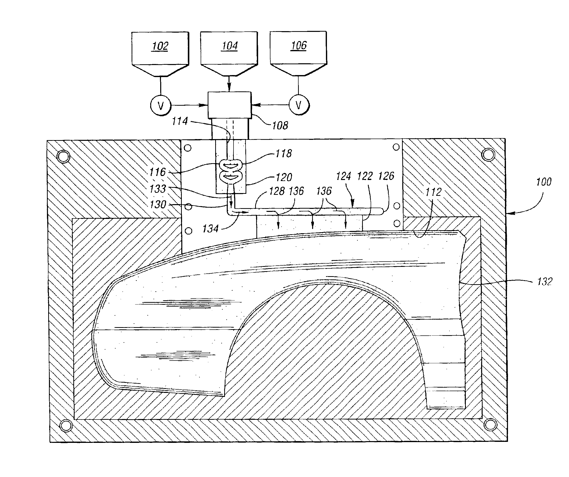
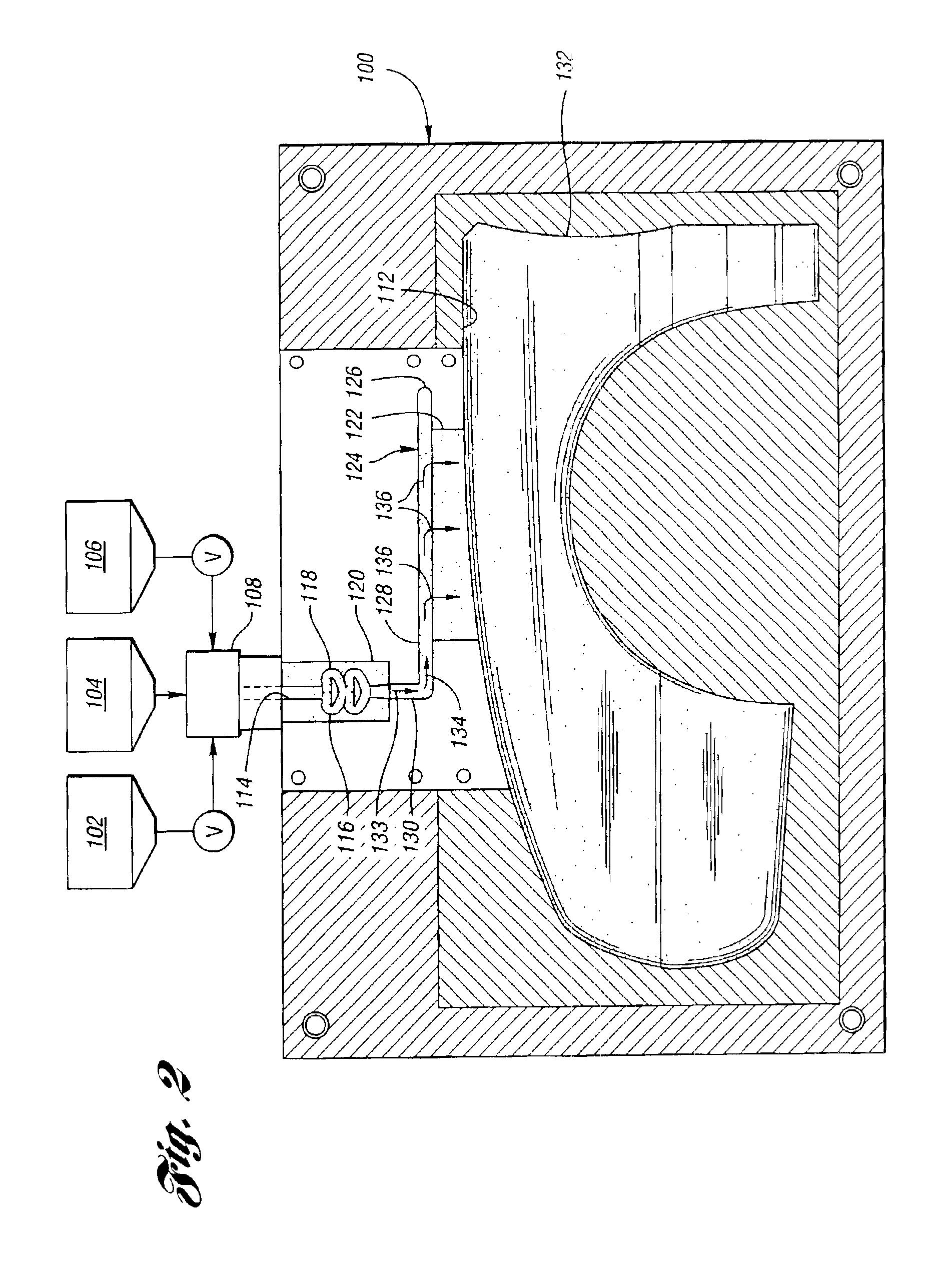
[0029]The present invention is generally an improved method, a mold used therein, and a part formed thereby wherein a novel gating system is used in the method and mold. Referring to FIGS. 2 and 3, the mold, generally indicated at 100, is typically used in a reaction injection molding system for making a reinforced polymeric article having reduced surface defects. The molding system typically includes sources 102, 104 and 106 of material which make up a curable, multi-component reaction fluid mixture such as a liquid urethane material. The urethane material may include a polyol resin component, an isocyanate constituent, a catalyst and a filler. An example of such commercially-available systems is Bayflex® 190, as previously mentioned, having a mica filler of approximately 18%.

[0030]Components or constituents of the urethane material are injected from the sources 102, 104 and 106 into a high pressure mixing apparatus 108 by way of respective metering devices. The fluid mixture with ...


PUM

PropertyMeasurementUnit
lengthaaaaaaaaaa
sizeaaaaaaaaaa
surface qualityaaaaaaaaaa

Abstract

A mold for use in a reaction injection molding method and system to make a reinforced polymeric article having reduced surface defects includes a novel gating system. The mold includes a pair of mold sections which define a closed, article-forming cavity, an injection aperture, and an after-mixer which helps to form a plurality of flow paths which extend downstream from the injection aperture toward the article-forming cavity to further mix a curable, multi-component, reaction fluid mixture including a filler. The flow paths are also at least partially defined by an elongated film gate and an elongated runner which extends along and is in fluid communication with the film gate along substantially the entire length of the film gate. The runner has a closed end and an open end into which a fluid mixture for the article flows for distribution by the runner into the film gate.

Description

BACKGROUND OF THE INVENTION[0001]1. Field of the Invention[0002]This invention relates to methods for making reinforced, polymeric articles in reaction injection molding systems, molds for use therein and articles produced thereby.[0003]2. Background Art[0004]Reaction injection molding (RIM) is a process by which highly chemically reactive liquids are injected into a mold where they quickly polymerize to form a coherent, molded article. Some of the most common RIM processes involve a rapid reaction between highly catalyzed polyether or polyester polyol and isocyanate constituents. The constituents are stored in separate tanks prior to molding and are first mixed in a mixhead upstream of a mold. Once mixed, they react rapidly to gel and then harden to form polyurethane polymers.[0005]As described in U.S. Pat. No. 5,753,155, rigid foam applications have struggled for many years with problems caused by liquid turbulence and splashings of the chemical stream into the part being foamed. ...

Claims


Application Information

Patent Timeline
Patent Type & Authority Patents(United States)
IPC IPC(8): B29C33/00B29C67/24
CPCB29C33/0072B29C33/0077B29C67/246B29L2031/3005B29K2709/10
Inventor HOWELL, TIMOTHY B.ROWLEY, ROBERT S.MURPHY, JOHN F.
Owner GLOBAL IP HLDG
Why Eureka
Try Eureka