Optical information recording medium, optical measuring method and optical information recording/reproducing method

a technology of optical information and recording medium, applied in the field of optical information recording medium, optical measuring method and optical information recording/reproducing method, can solve the problems of deteriorating the quality of reproduced signals, affecting the farther inside information layer by the nearer information layer, and unable to perform accurate recording

Inactive Publication Date: 2005-05-17
PANASONIC CORP
View PDF9 Cites 9 Cited by
  • Summary
  • Abstract
  • Description
  • Claims
  • Application Information

AI Technical Summary

Benefits of technology

[0011]The present invention is intended to solve these problems by providing an optical information recording medium and the like permitting accurate recording and reproduction of data onto and out of an information layer farther inside in a multi-layered recording medium.
[0070]By such measuring methods of the 12-th or 13-th present invention the amount of the change of the transmittance of the nearer positioned information layer can be easily obtained without measuring the transmission foctor.
[0092]By such measuring methods of the 16-th or 17-th present invention the amount of the change of the transmittance of the nearer positioned information layer can be easily obtained without measuring the transmission foctor.

Problems solved by technology

However, when recording is to be done onto an information layer farther inside from the laser incidence side by the conventional method, there is a fear that the farther inside information layer is affected by the nearer information layer.
Accordingly there is a problem that, when recording is to be done on a farther information layer, the intensity of the laser beam reaching the farther information layer varies with the ratio between the amorphous area and the crystalline area in the laser spot on the nearer information recording layer, making it impossible to perform accurate recording.
A further problem is that, when data on the farther information layer are to be reproduced, the change in the transmittance depending on the recording state of the nearer information layer invites deterioration in the quality of reproduced signals.

Method used


Image

  • Optical information recording medium, optical measuring method and optical information recording/reproducing method
  • Optical information recording medium, optical measuring method and optical information recording/reproducing method
  • Optical information recording medium, optical measuring method and optical information recording/reproducing method

Examples


second embodiment

(Second Embodiment)

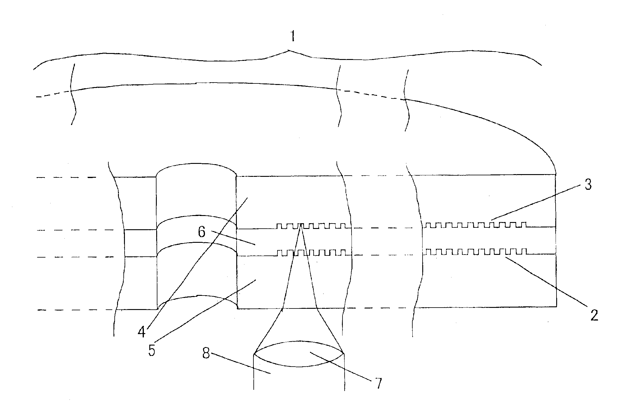
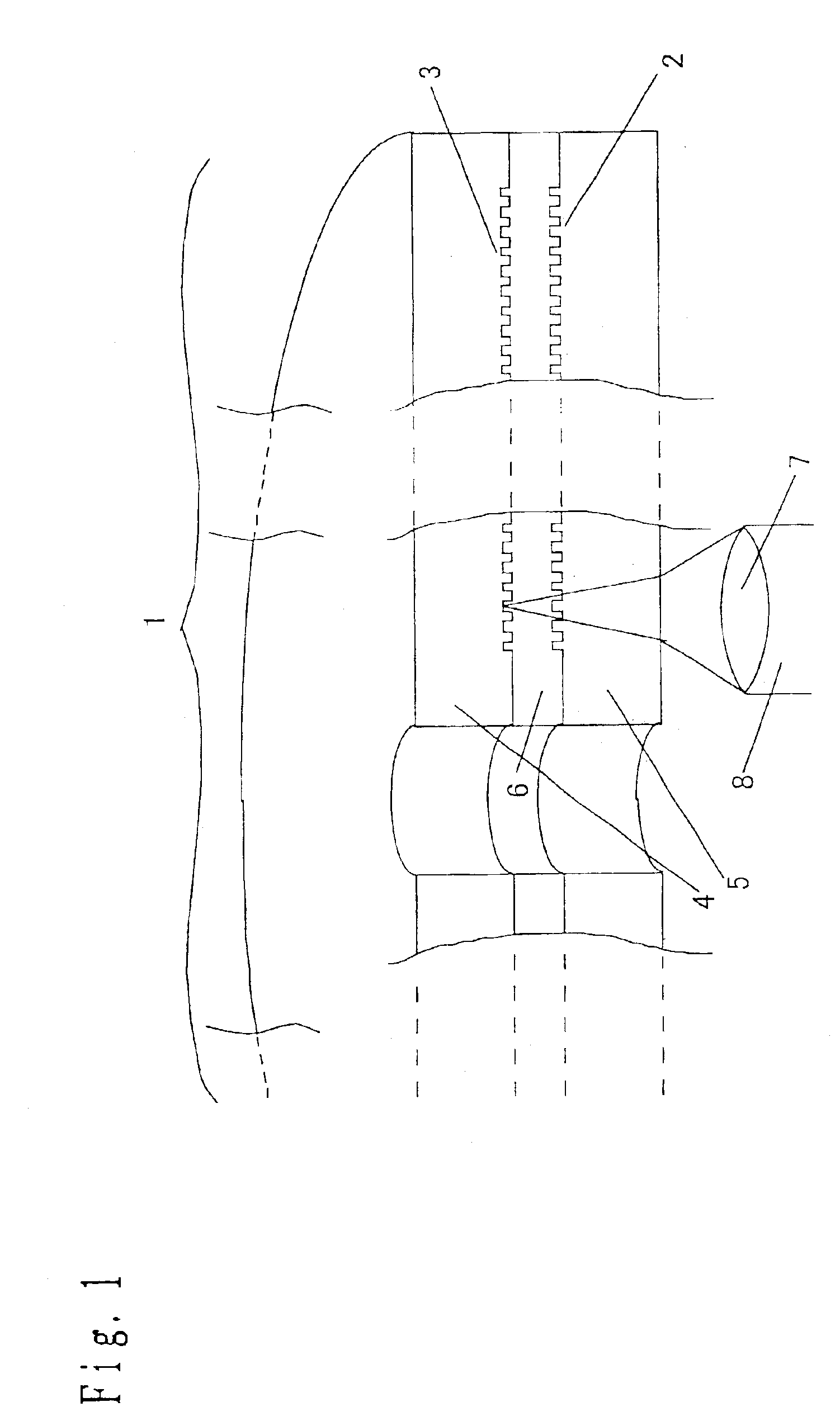
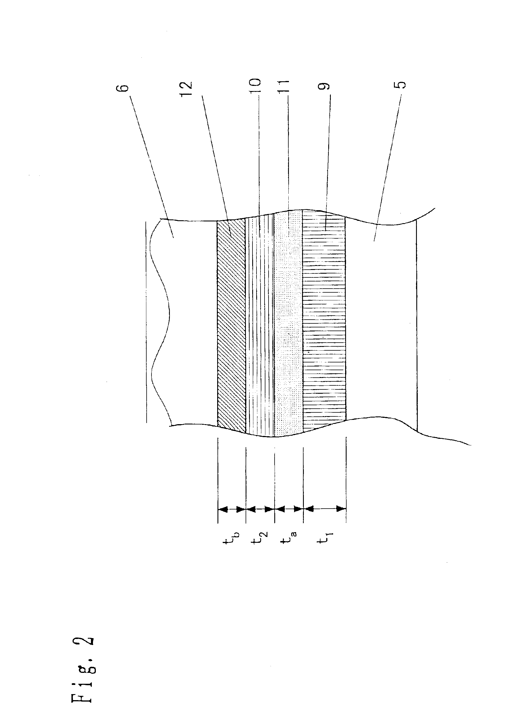
[0181]FIG. 5 is a sectional view showing an example of configuration of the first information layer 2, which constitutes the nearer information layer in FIG. 1 as viewed from the incidence side of the laser beam. This mode differs from the first embodiment in that a third dielectric layer 13 is provided over the reflecting layer 12. FIG. 6 is a diagram in which changes of the average transmittance (Ta+Tc) / 2 and of the transmittance ratio (Tc−Ta) / Tc are plotted where the thickness of the recording layer is set to 10 nm, the thickness of the reflecting layer is set to 10 nm, the thickness of the third dielectric layer is set to 10 nm and the film thicknesses of the first dielectric layer and the second dielectric layer are varied. To compare FIG. 6 with FIG. 4, in spite of the same thicknesses of the recording layer and of the reflecting layer, the provision of the third dielectric layer has expanded the area in which the absolute value of the transmittance ratio (T...


PUM

PropertyMeasurementUnit
wavelengthaaaaaaaaaa
thicknessaaaaaaaaaa
thicknessaaaaaaaaaa

Abstract

An optical information recording medium having two or more information layers, wherein the irradiation of either the information layer with a laser beam converging thereon causes information signals to be recorded or reproduced; the nearer positioned information layer than the farthest information layer as viewed from the incidence side of the laser beam has a recording layer varying between two optically detectable states, and0≦|Tc−Ta| / Tc≦0.1where Tc is the transmittance of the nearer positioned information layer when the recording layer is in state (a) and Ta, the transmittance, when it is in state (b). This makes possible accurate accurately recording and reproduction of information onto and out of the farther information layer irrespective of whether or not any information is recorded on the nearer information layer.

Description

BACKGROUND OF THE INVENTION[0001]1. Field of the Invention[0002]The present invention relates to an optical information recording medium and the like, such as an optical disk.[0003]2. Related Art of the Invention[0004]In recent years, optical disks, optical cards and optical tapes have been proposed and developed as media for optically recording information. Above all, optical disks are attracting note as media capable of recording and reproducing information in large capacity and in high density.[0005]One of the erasable optical disk types is a phase change type optical disk. The recording film for use in the phase change type optical disk takes on either an amorphous state or a crystalline state depending on the conditions of heating or cooling with a laser beam, and the two states are reversible between each other. The optical constant of the recording film is different between the amorphous state and the crystalline state. In the phase change type optical disk, one or the other ...

Claims


Application Information

Patent Timeline
Patent Type & Authority Patents(United States)
IPC IPC(8): B32B3/02G01N21/88G01N21/95G01N21/84G11B7/26G11B7/00G11B7/24G01N21/59G11B7/0037G11B7/0045G11B7/005G11B7/24035G11B7/24038G11B7/241G11B7/243G11B7/258G11B7/259G11B11/105
CPCG01N21/5911G11B7/24035G11B7/24038Y10T428/21G11B7/00454G11B7/0052G11B7/24G11B7/241G11B7/258G11B7/259G11B7/268G11B11/10584G11B2007/0013G11B2007/24312G11B2007/24314G11B2007/24316G11B7/00375G11B7/004G11B7/2433
Inventor NARUMI, KENJINISHIUCHI, KENICHIMIYAGAWA, NAOYASUKOJIMA, RIENISHIHARA, TAKASHIYAMADA, NOBORU
Owner PANASONIC CORP
Why Eureka
Try Eureka