Thin film resonators

a thin film, electromagnetic resonator technology, applied in the direction of resonators, superconductors/hyperconductors, electrical equipment, etc., can solve the problems of reducing and affecting the efficiency of resonators

Inactive Publication Date: 2005-05-17
ILLINOIS SUPERCONDUCTOR CORP
View PDF51 Cites 6 Cited by
  • Summary
  • Abstract
  • Description
  • Claims
  • Application Information

AI Technical Summary

Problems solved by technology

One major problem associated with the fabrication of thin film resonators is the variation in the thickness of the dielectric substrate.
Tuning of filters designed using such resonators is a very tedious task even for experienced filter engineers, because one has to tune not only the coupling coefficient between the resonators but also the resonant frequency of the individual resonators.
Another issue pertinent to thin film filters is the miniaturization of the resonator structure used to design such filters.
As the resonant frequency of a microstrip resonator decreases, and, therefore, the resonant wavelength increases, it is necessary to use larger size microstrip resonators, which necessitates the use of bulky resonators to achieve lower resonant frequencies.

Method used


Image

  • Thin film resonators
  • Thin film resonators
  • Thin film resonators

Examples


Embodiment Construction

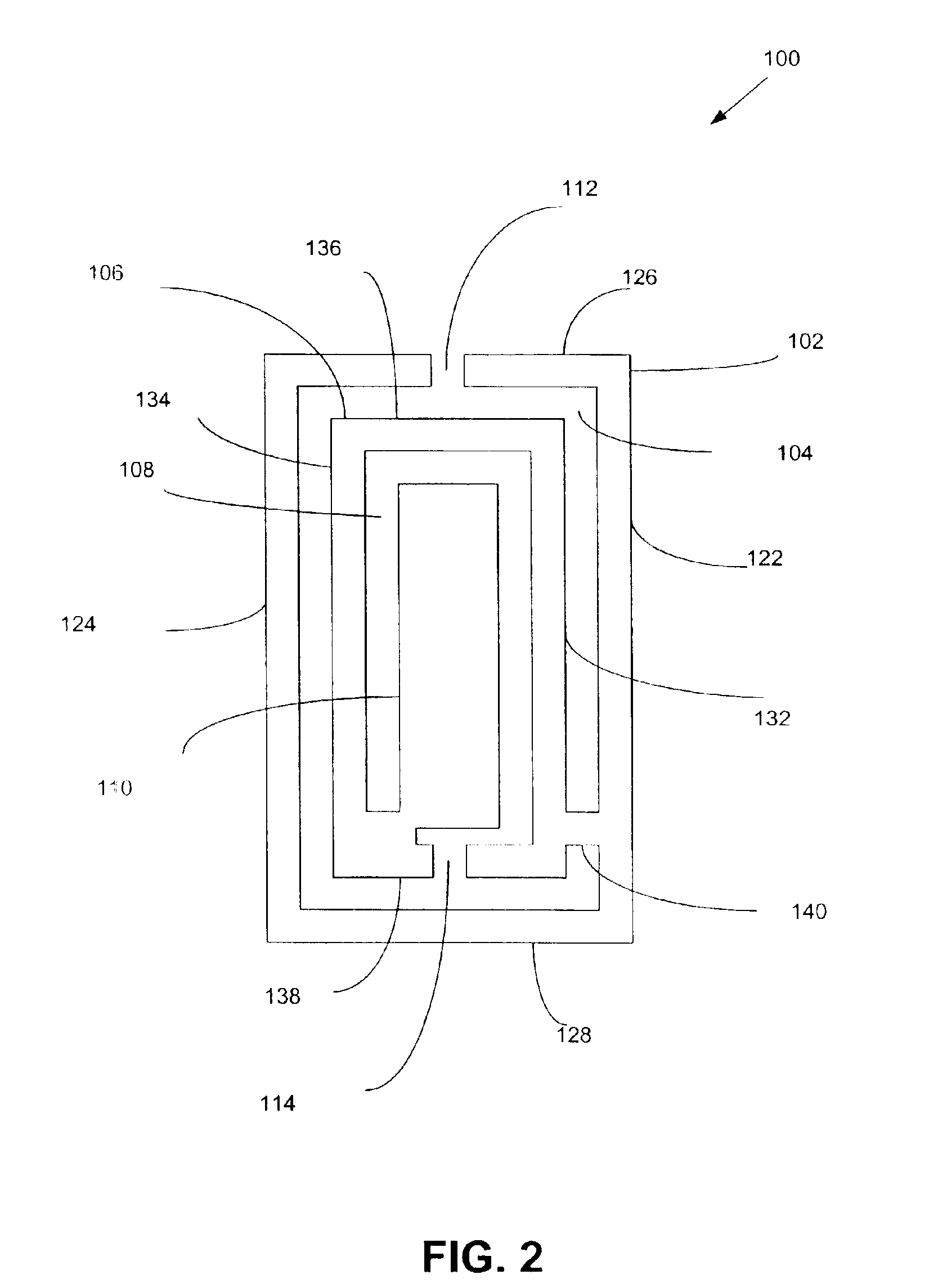
[0026]As disclosed in detail hereinafter, a resonator is provided which integrates a microstrip resonator structure and a coplanar resonator structure. FIG. 2 illustrates an exemplary resonator 100 including a first outer loop 102, a first open slot 104, a first inner loop 106 and a second open slot 108. The first open slot 104 is located within the first outer loop 102. Similarly, the second open slot 108 is located within the first inner loop 106. The resonator 100 further includes a first rectangular strip 110 located within the second open slot 108.

[0027]The first outer loop 102 of the resonator 100 includes a first opening 112, while the first inner loop 106 of the resonator 100 includes a second opening 114. The first outer loop 102 and the first inner loop 106 of the resonator 100 illustrated in FIG. 2 may be fabricated from high temperature superconductive materials, such as YBa2Cu3O7-δ. However, in an alternate embodiment of the resonator 100, the first outer loop 102 and t...


PUM

PropertyMeasurementUnit
lengthaaaaaaaaaa
lengthaaaaaaaaaa
widthaaaaaaaaaa

Abstract

A thin film resonator which combines a microstrip resonator structure and a coplanar resonator structure to form an integrated resonator structure. The resonant frequency of this resonator structure is independent of the substrate thickness within a certain thickness range. This resonator structure also has a very economical size, as compared to other existing resonator designs. Different coupling configurations between the resonators are shown with the resulting coupling coefficients. Also a two-pole, four-pole and an eight-pole filter are designed using the thin film resonator and the insertion loss and return loss characteristics for various filters are shown.

Description

TECHNICAL FIELD[0001]The present disclosure relates generally to electromagnetic resonators, and more particularly, to microstrip electromagnetic resonators.BACKGROUND ART[0002]Conventional resonant cavity filters consist of an outer housing made of an electrically conductive material and one or more resonant elements, or resonators, are mounted inside the housing. The resonators may be mounted within the cavity using, for example, a dielectric material. Electromagnetic energy is coupled through a first coupling mechanism in the housing to a first resonator and then to any additional resonators in the housing. A second coupling mechanism is used to output the electromagnetic energy from the housing.[0003]Resonators are often used in filters to pass or reject certain signal frequencies. The particular design, shape, materials and spacing of the housing, the resonant elements, and the apertures between resonant elements determine the signal frequencies passed through the filter, as we...

Claims


Application Information

Patent Timeline
Patent Type & Authority Patents(United States)
IPC IPC(8): H01P1/203H01P7/08H01P1/20
CPCH01P1/20336H01P7/082H01P1/20381
Inventor YI, HUAI REN
Owner ILLINOIS SUPERCONDUCTOR CORP
Why Eureka
Try Eureka