Resonator filter with improved adjacent channel selectivity

a filter and adjacent channel technology, applied in piezoelectric/electrostrictive/magnetostrictive devices, piezoelectric/electrostriction/magnetostriction machines, electrical apparatus, etc., can solve the problem of unsatisfactory effect, unacceptable tx suppression, and filter cannot be utilized as tx filters, etc. problem, to achieve the effect of improving the adjacent channel selectivity

Inactive Publication Date: 2005-05-17
SNAPTRACK
View PDF12 Cites 29 Cited by
  • Summary
  • Abstract
  • Description
  • Claims
  • Application Information

AI Technical Summary

Benefits of technology

[0006]It is therefore an object of the present invention to provide a resonator filter that exhibits an improved adjacent channel selectivity and in which, in particular, disturbing spikes at the low-frequency side of the pass-band are eliminated in the near stop-band.

Problems solved by technology

The TX suppression is unacceptably slight due to the spikes in the TX region, particularly given single-track DMS filters, so that the filter cannot be utilized as a TX filter.
The desired effect, however, is not adequate and, in particular, a satisfactory possibility of eliminating these disturbing spikes has not yet been found for one-track DMS filters.

Method used


Image

  • Resonator filter with improved adjacent channel selectivity
  • Resonator filter with improved adjacent channel selectivity
  • Resonator filter with improved adjacent channel selectivity

Examples


Embodiment Construction

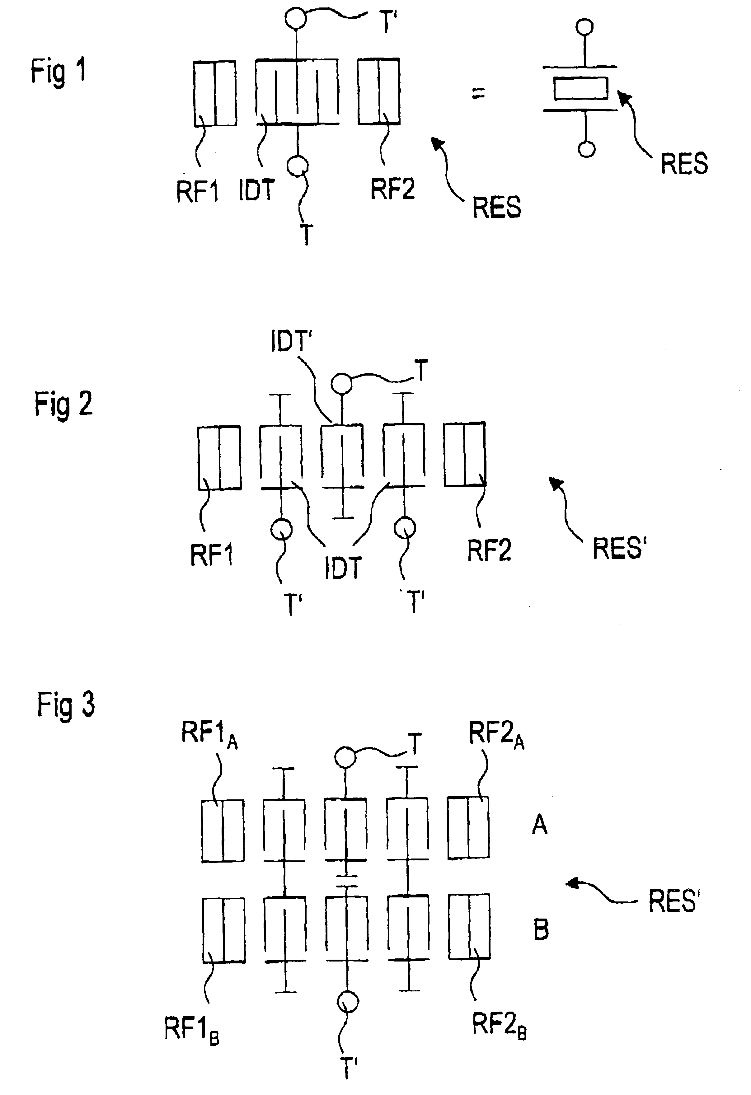
[0047]FIG. 1 shows a single-port resonator that can be part of an inventive resonator filter. The left part of FIG. 1 indicates the metallization on the surface of a piezoelectric substrate, and the right part of the FIG. 1 indicates the circuit symbol employed for it.

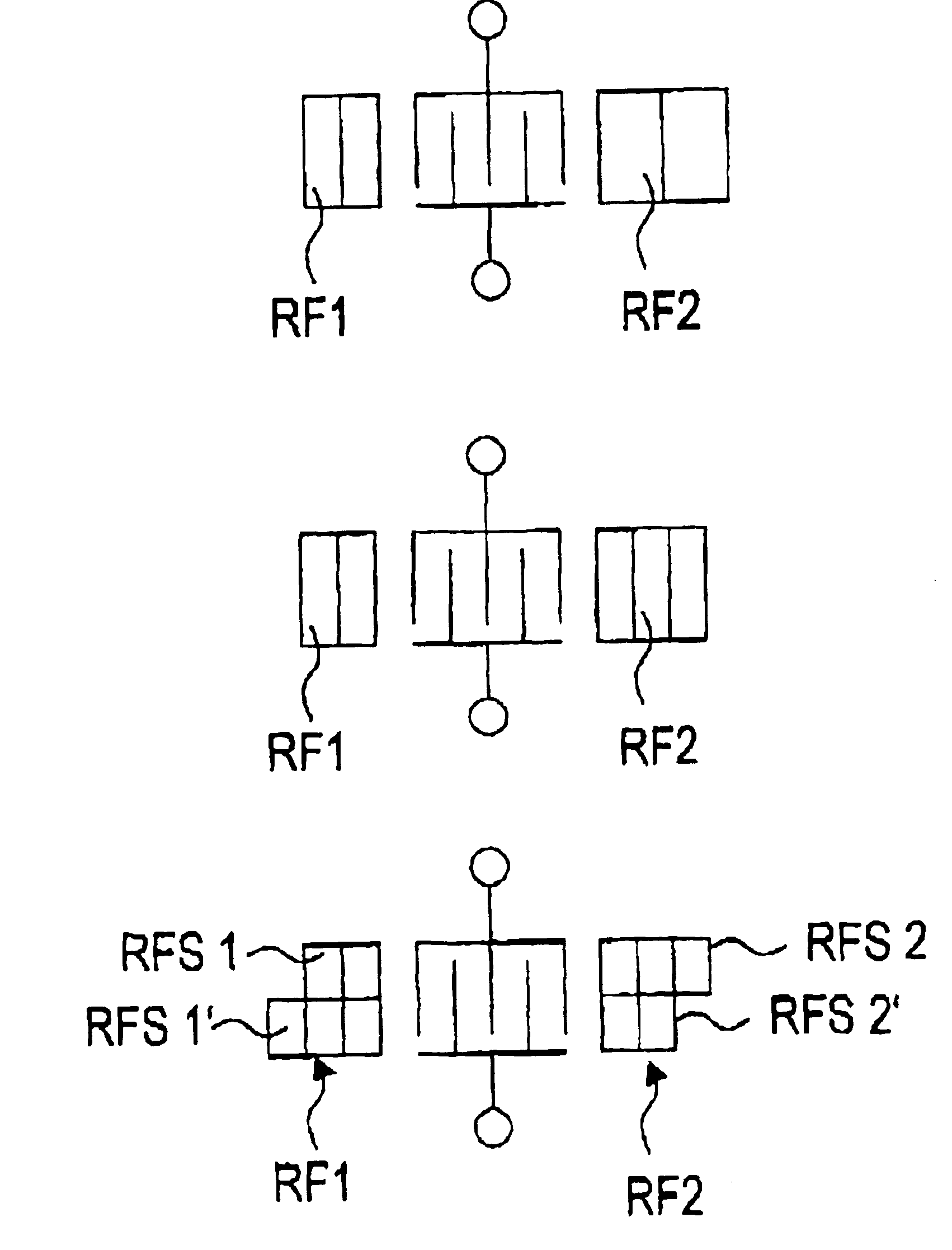
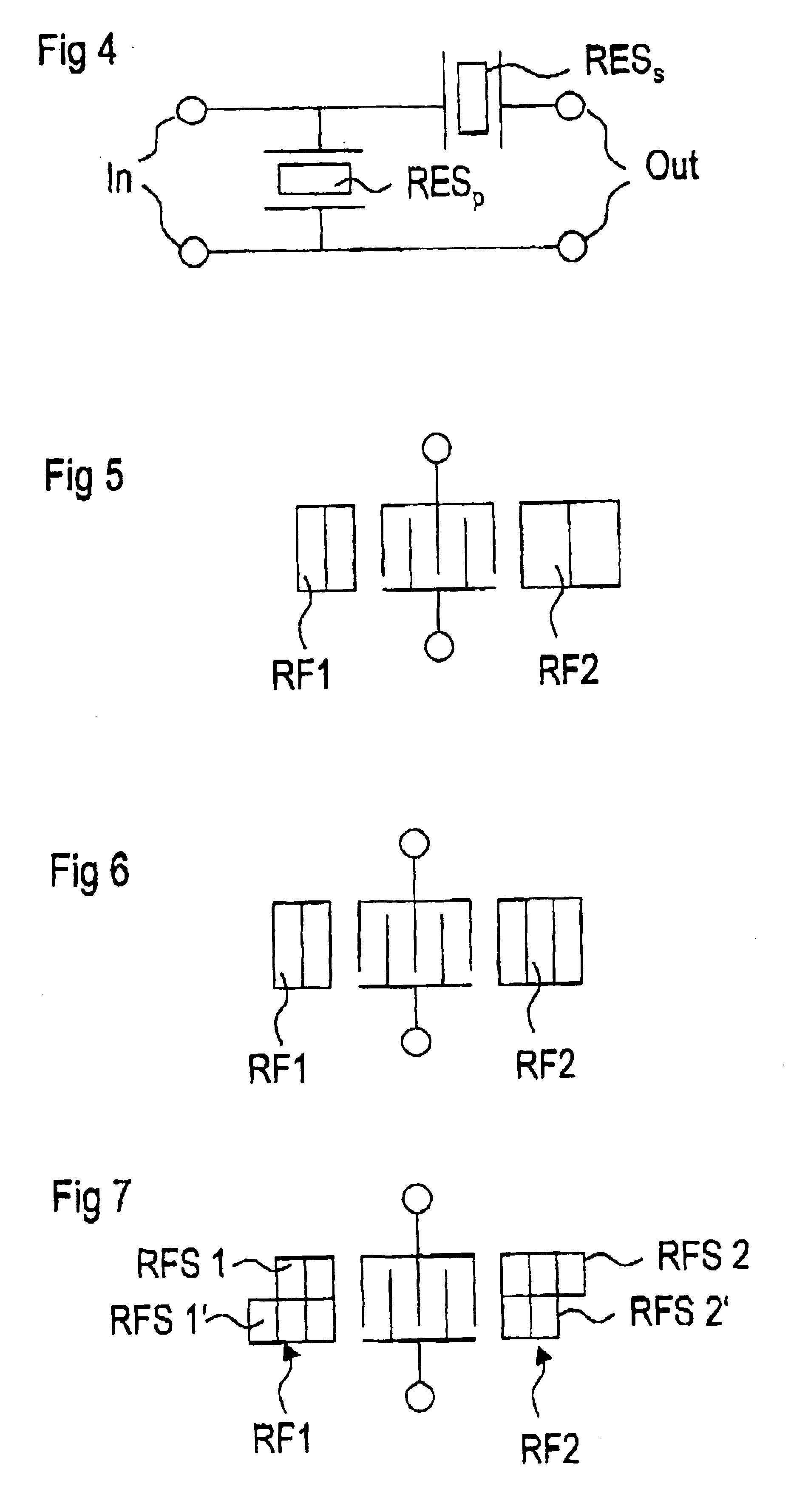
[0048]A single-port resonator is composed of an interdigital transducer IDT that is in turn composed of two electrode combs that have their “teeth” inserted into one another. Each comb is connected to a respective terminal T, T′. A respective reflector RF1, RF2 is arranged at both sides of the interdigital transducer IDT. This is composed of what is usually a regular stripe pattern whose stripes—as indicated in FIG. 1—can be electrically shorted. Overall, the reflector can be connected to ground or can be without a connection to a reference potential. Given this simple resonator, the two reflectors RF1 and RF2 inventively differ in their reflection function such that the minimums of the reflection function lie at diffe...


PUM


Abstract

For improving the adjacent channel selectivity of a resonator filter, reflectors of resonators are differently designed so that the minimums of the reflection functions of different reflectors of a resonator are shifted relative to one another and preferably compensate with the corresponding maximum of the respectively other reflection function. This reduces noise spikes at the low-frequency side of the pass-band of corresponding resonator filters and, thus, improves the adjacent channel selectivity.

Description

BACKGROUND OF THE INVENTION[0001]1. Field of the Invention[0002]The invention relates to resonant filters for improving adjacent channel selectivity.[0003]2. Description of the Related Art[0004]Spikes with slight attenuation behavior that negatively influence the adjacent channel selectivity in a particular frequency range are usually found at the left side of the pass-band in the transfer function of Dual Mode Surface acoustic wave SAW (DMS) filters. When, for example, such a filter is utilized as an input filter in the front end of a mobile radiotelephone device, then the disturbing spikes in the transfer function lie in the region of the transmit (“TX”) band that is provided for the incoming signals. The TX suppression is unacceptably slight due to the spikes in the TX region, particularly given single-track DMS filters, so that the filter cannot be utilized as a TX filter.[0005]For solving this problem, DMS filters with a plurality of cascaded tracks were previously utilized, wh...

Claims


Application Information

Patent Timeline
Patent Type & Authority Patents(United States)
IPC IPC(8): H03H9/00H03H9/64
CPCH03H9/6483H03H9/6469H03H9/6436H03H9/643
Inventor DETLEFSEN, ANDREAS
Owner SNAPTRACK
Why Eureka
Try Eureka