Coupled resonator filters formed by micromachining

a technology of micromachining and filter, applied in the direction of waveguide type devices, resonances, basic electric elements, etc., can solve the problems of filter type, manual adjustment of filter, insufficient precision of conventional machining,

Inactive Publication Date: 2006-10-19
KRATOS INTEGRAL HLDG LLC
View PDF12 Cites 19 Cited by
  • Summary
  • Abstract
  • Description
  • Claims
  • Application Information

AI Technical Summary

Benefits of technology

[0017] The above and other features of the invention including various and novel details of construction and combination of parts will now be more fully described with reference to the accompanying drawings and pointed out in the claims. It will be understood that the particular features embodying the invention are shown by way of illustration only and not as a limitation of the invention. The principle and features of this invention may be employed in varied and numerous embodiments without departing from the scope of the invention.

Problems solved by technology

However, because conventional machining is not precise enough to exactly give the desired filter response, tuning structures such as screws are needed to “tune up” a filter to give it an optimized response.
A disadvantage of this type of structure is that it requires manual adjustment of the filter by a technician to give the optimum response.
However, this type of filter suffers from the thinness of the resonator line (the deposited metal is usually no more than a few microns thick) and the edge coupling of the resonators.
This concentrates the currents along the edge of the resonator, which increases the ohmic losses, and reduces the resonator Q. This design also can be susceptible to small mechanical vibrations known as microphonics, which can modulate a signal passed through the filter.

Method used


Image

  • Coupled resonator filters formed by micromachining
  • Coupled resonator filters formed by micromachining
  • Coupled resonator filters formed by micromachining

Examples


Embodiment Construction

[0027] The following description of illustrative non-limiting embodiments of the invention discloses specific configurations, features, and operations. However, the embodiments are merely examples of the present invention, and thus, the specific features described below are merely used to more easily describe such embodiments and to provide an overall understanding of the present invention.

[0028] Accordingly, one skilled in the art will readily recognize that the present invention is not limited to the specific embodiments described below. Furthermore, the description of various configurations, features, and operations of the present invention that are known to one skilled in the art are omitted for the sake of clarity and brevity. Also, it is to be understood that the phraseology and terminology employed herein is for the purpose of description and should not be regarded as limiting.

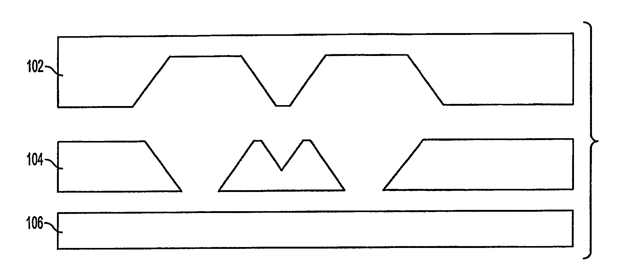
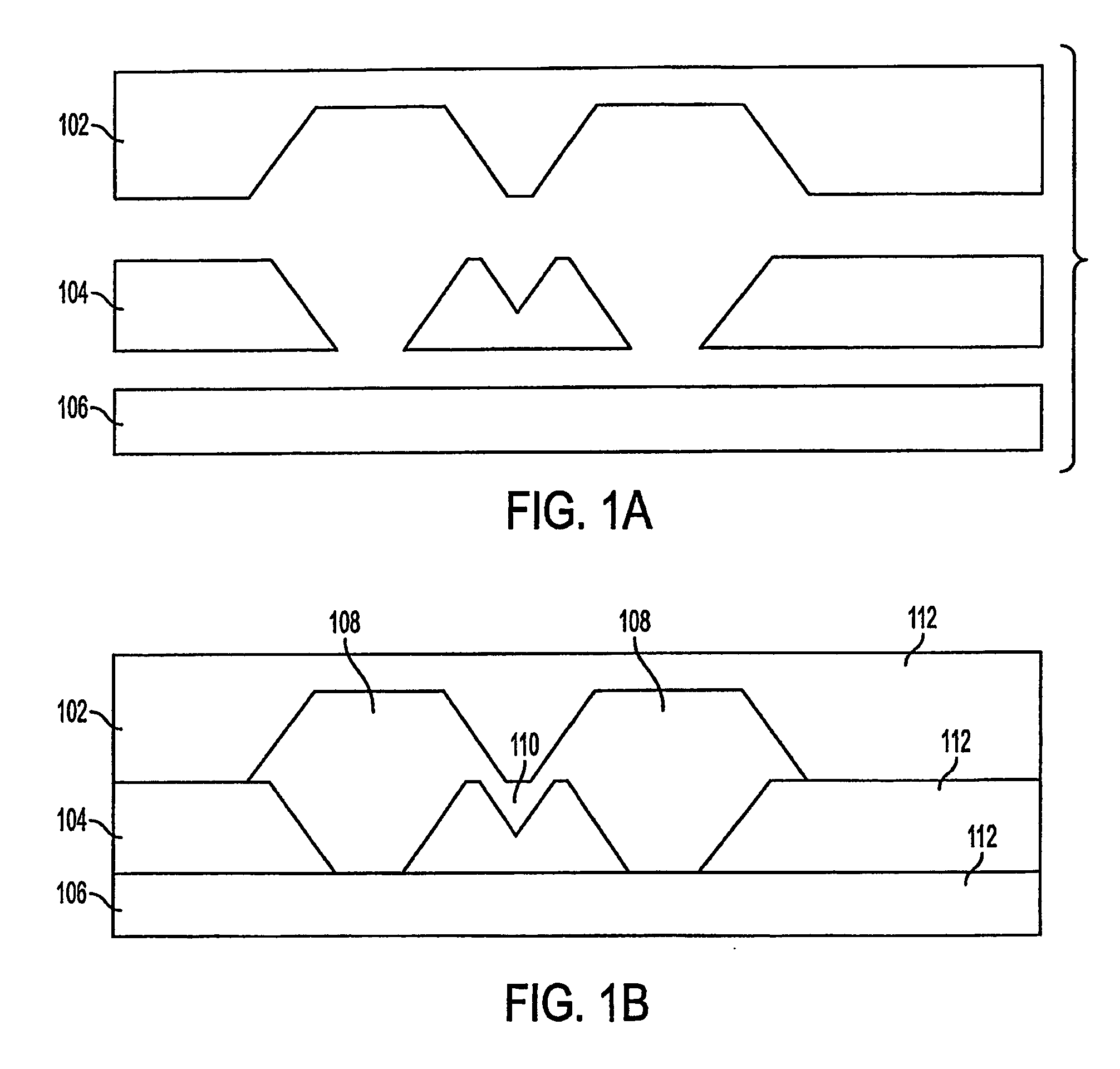
[0029] An illustrative embodiment of the present invention is described with reference to a bandpa...


PUM


Abstract

A resonator filter assembly is provided having a first wafer (102), a second wafer (104) and a third wafer (106). A plurality of pits are etched in the first and second wafer (102, 104) and arranged such that a plurality of resonant cavities (108) are formed with a coupling cavity (110) disposed between the resonant cavities (108). By altering the dimensions of the resonant and coupling cavities (108, 110), the frequency characteristics of the filter can be adjusted as desired.

Description

CROSS-REFERENCE TO RELATED APPLICATIONS [0001] This application claims benefit of Provisional Application No. 60 / 424,620 filed Nov. 7, 2002, the disclosure of which is incorporated herein by reference.BACKGROUND OF THE INVENTION [0002] 1. Field of the Invention [0003] The present invention relates to coupled resonator filters. More particularly, the present invention relates to coupled resonator filters formed by micromaching techniques and a method for making the same. [0004] 2. Related Art [0005] Microwave filters are devices that pass some microwave signals and reject others, based on the frequency of the signal. Conventionally, microwave filters are made using resonate structures in different arrangements. Depending on the arrangement of the resonant structures, filters can be made which are low-pass (i.e., pass lower frequencies and reject higher frequencies), high pass (i.e., pass higher frequencies and reject lower frequencies), band pass (i.e., pass a limited range of freque...

Claims


Application Information

Patent Timeline
Patent Type & Authority Applications(United States)
IPC IPC(8): H01P7/06H01P1/20H01P11/00
CPCH01P1/208H01P1/2088H01P11/007H01P11/002H01P7/065
Inventor KOH, PHILIP J.NEMETH, DAVID T.
Owner KRATOS INTEGRAL HLDG LLC
Why Eureka
Try Eureka