Matching a resonant frequency of a resonant cavity to a frequency of an input voltage

A technology of resonant frequency and input voltage, which is applied in the field of matching the resonant frequency of the resonant cavity and the frequency of the input voltage, can solve the problem of non-uniform particle acceleration

Active Publication Date: 2010-12-29
MEVION MEDICAL EQUIP CO LTD
View PDF4 Cites 64 Cited by
  • Summary
  • Abstract
  • Description
  • Claims
  • Application Information

AI Technical Summary

Problems solved by technology

Consequently, the acceleration of the particles becomes non-uniform and ...

Method used


Image

  • Matching a resonant frequency of a resonant cavity to a frequency of an input voltage
  • Matching a resonant frequency of a resonant cavity to a frequency of an input voltage
  • Matching a resonant frequency of a resonant cavity to a frequency of an input voltage

Examples


Embodiment Construction

[0028] A synchrocyclotron-based system is described herein. However, the circuits and methods described herein can be used with any type of cyclotron.

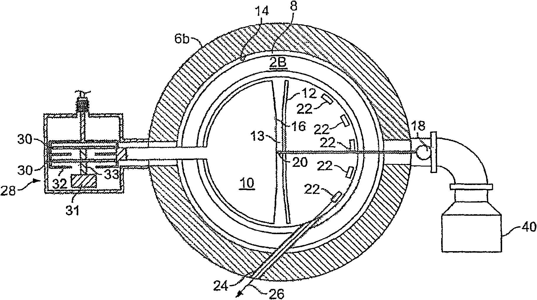
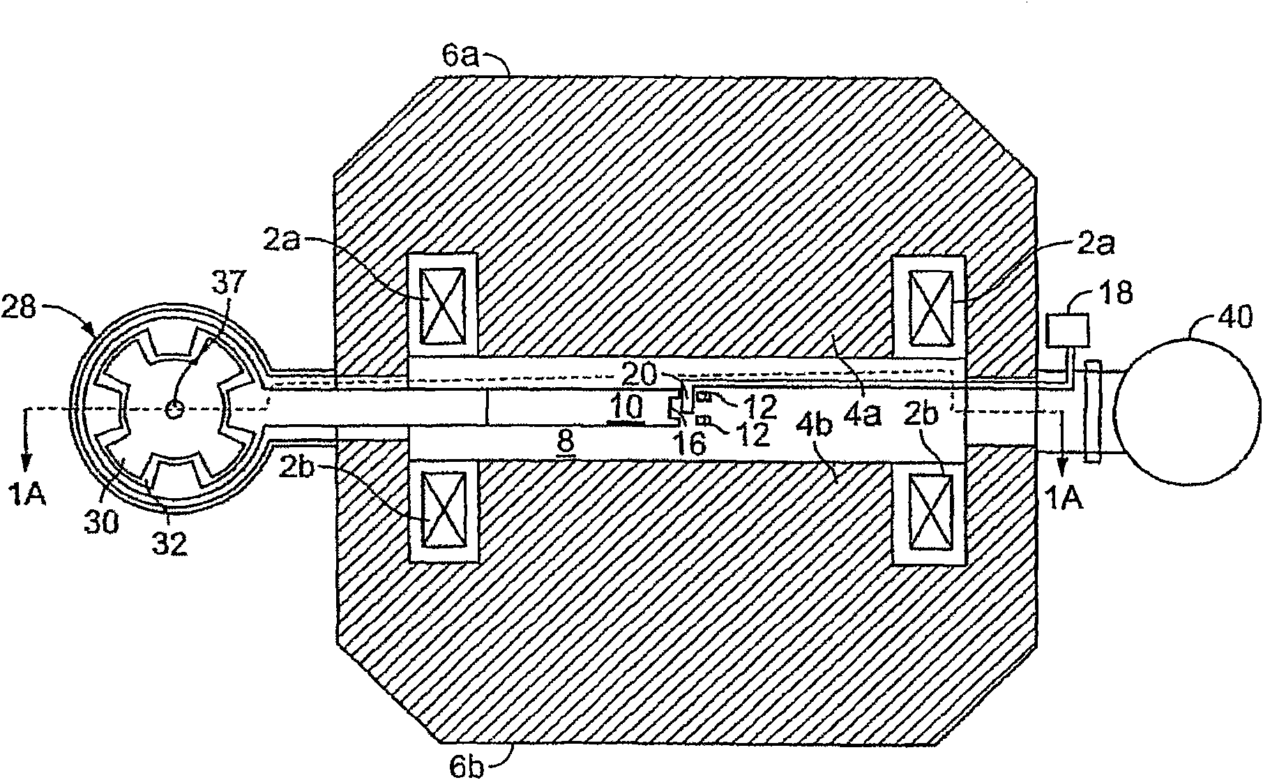
[0029] refer to Figure 1A and Figure 1B , the synchrocyclotron comprises electrical coils 2a and 2b surrounding two spaced apart metal poles 4a and 4b configured to generate a magnetic field. The poles 4a and 4b are defined by two opposing yoke portions 6a and 6b (as shown in cross-section). The spacing between the poles 4a and 4b defines a vacuum chamber 8, or a separate vacuum chamber may be installed between the poles 4a and 4b. The magnetic field strength is generally a function of the distance from the center of the vacuum chamber 8 and is mainly determined by the choice of the geometry of the coils 2a and 2b and the shape and material of the poles 4a and 4b.

[0030] The accelerating electrodes are defined as a dee 10 and a dee 12 with a gap 13 between them. The dee 10 is connected to an alternating voltage potenti...


PUM


Abstract

A synchrocyclotron includes magnetic structures that define a resonant cavity, a source to provide particles to the resonant cavity, a voltage source to provide radio frequency (RF) voltage to the resonant cavity, a phase detector to detect a difference in phase between the RF voltage and a resonant frequency of the resonant cavity that changes over time, and a control circuit, responsive to the difference in phase, to control the voltage source so that a frequency of the RF voltage substantially matches the resonant frequency of the resonant cavity.

Description

technical field [0001] This patent application describes matching the resonant frequency of a resonant cavity to the frequency of the voltage input to the resonant cavity. Background technique [0002] To accelerate charged particles to high energies, many types of particle accelerators have been developed. One type of particle accelerator is a cyclotron. A cyclotron accelerates charged particles in an axial magnetic field by applying an alternating voltage to one or more dees in a vacuum chamber. The name "D-shaped electrodes" is a description of the shape of the electrodes in early cyclotrons, although in some cyclotrons they may not resemble the letter D. The spiral tracks created by the accelerated particles are perpendicular to the magnetic field. As the particles spiral outward, an accelerating electric field is applied at the gap between the dees. A radio frequency (RF) voltage generates an alternating electric field across the gap between the dees. The RF voltag...

Claims


Application Information

Patent Timeline
IPC IPC(8): H05H13/02
CPCH03L7/00H05H13/02
Inventor 查尔斯·D·奥尼尔亚当·C·莫尔赞约翰·J·文森特
Owner MEVION MEDICAL EQUIP CO LTD
Why Eureka
Try Eureka