Coupled lamb wave resonators filter

a resonator filter and lamb wave technology, applied in the field of filters, can solve the problems of large manufacturing, cost and reliability problems, and the width of the 4 passband obtained at the output is also too large for channel filtering, so as to facilitate manufacturing and improve the reliability of the filter

Active Publication Date: 2010-09-28
STMICROELECTRONICS SRL
View PDF10 Cites 19 Cited by
  • Summary
  • Abstract
  • Description
  • Claims
  • Application Information

AI Technical Summary

Benefits of technology

[0008]Another object of the invention is to provide a filter that can be directly integrated onto an integrated circuit (above IC integration) to improve performance by reducing losses on filtered signals, and to reduce the costs and size of circuits.
[0026]The coupled Lamb wave resonator filter may also include at least a Bragg mirror acoustically coupled to one of the resonators. The resonator may be arranged between the Bragg mirror and another resonator. The Bragg mirror can reduce parasitic resonances present in the output spectrum from the filter related to harmonics in
[0030]A single resonant layer can form resonant layers of Lamb wave resonators, and when the filter comprises at least one Bragg mirror and / or at least one periodic lattice, the resonant material of the Bragg mirror(s) and / or the periodic lattice(s). Thus, the reliability of the filter can be improved, and its manufacturing can be facilitated using only a single resonant layer.

Problems solved by technology

This causes manufacturing, cost and reliability problems.
Finally, when it is required to filter at intermediate frequencies, i.e., at frequencies between about 1 MHZ and 500 MHz, the thicknesses necessary for this type of filter become much too large for manufacturing.
Therefore, the width of the 4 passband obtained at the output is also too large for channel filtering.
The dimensions necessary for this type of filter are also much too large when it is required to filter at intermediate frequencies.

Method used


Image

  • Coupled lamb wave resonators filter
  • Coupled lamb wave resonators filter
  • Coupled lamb wave resonators filter

Examples


first embodiment

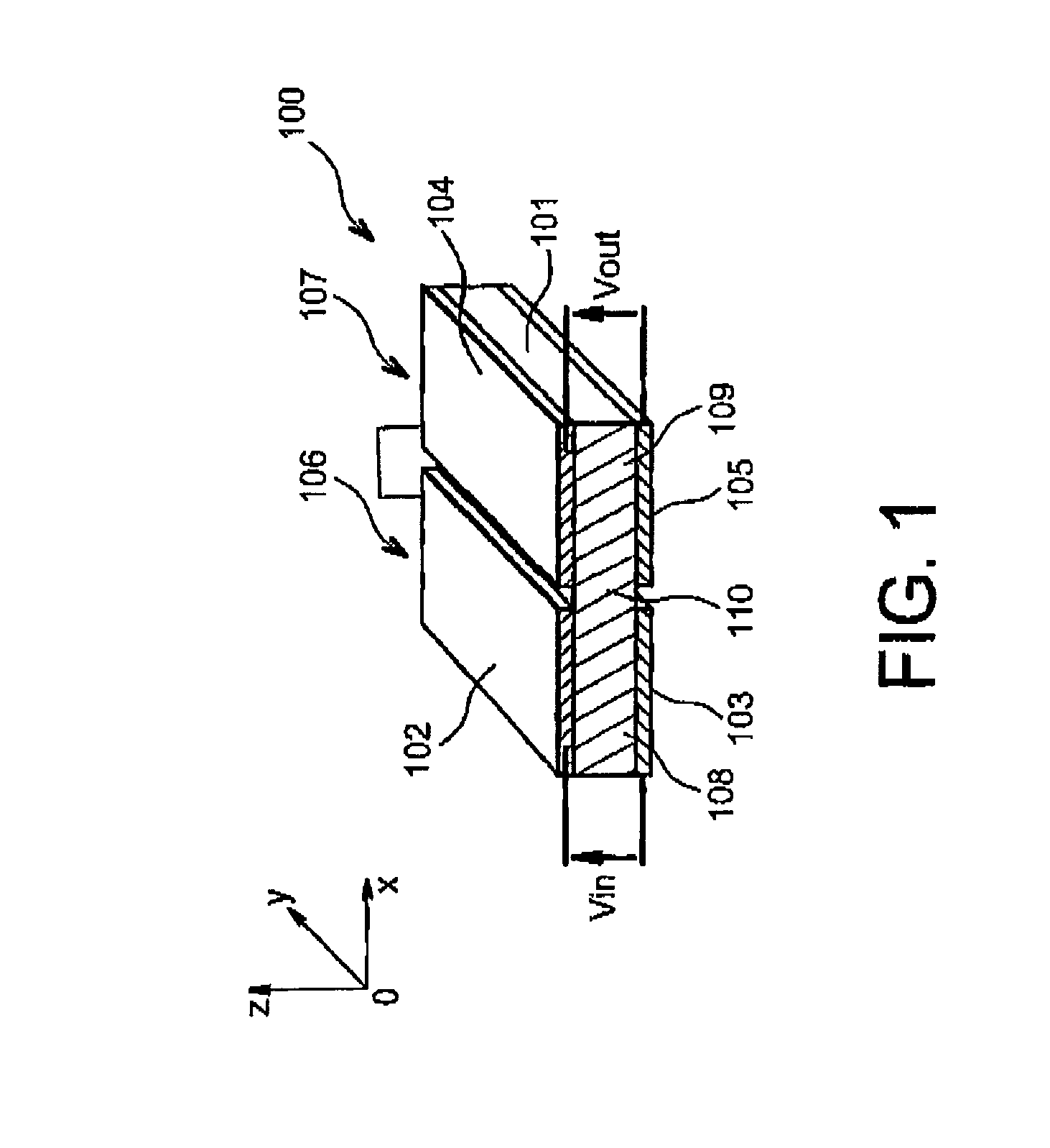
[0037]Referring first to FIG. 1, a coupled Lamb wave resonator filter 100 is shown. In the following description, the coupled Lamb wave resonator filter 100 is described without a periodic lattice between its resonators.

[0038]The coupled Lamb wave resonator filter 100 comprises a resonant layer 101 that may be based on a piezoelectric material such as aluminium nitride and / or zinc oxide or even PZT. Two electrodes 102 and 104 are arranged adjacent to each other on the resonant layer 101. In FIG. 1, these two electrodes 102 and 104 are separated from each other. Two other electrodes 103 and 105 are arranged adjacent to each other under the resonant layer 101. These other two electrodes 103 and 105 are also separated from each other. In FIG. 1, all electrodes 102 to 105 have the same length and are aligned vertically in pairs, and can be made conventionally, for example based on platinum, aluminium, molybdenum and / or tungsten.

[0039]At least one of the faces of the first resonant laye...

second embodiment

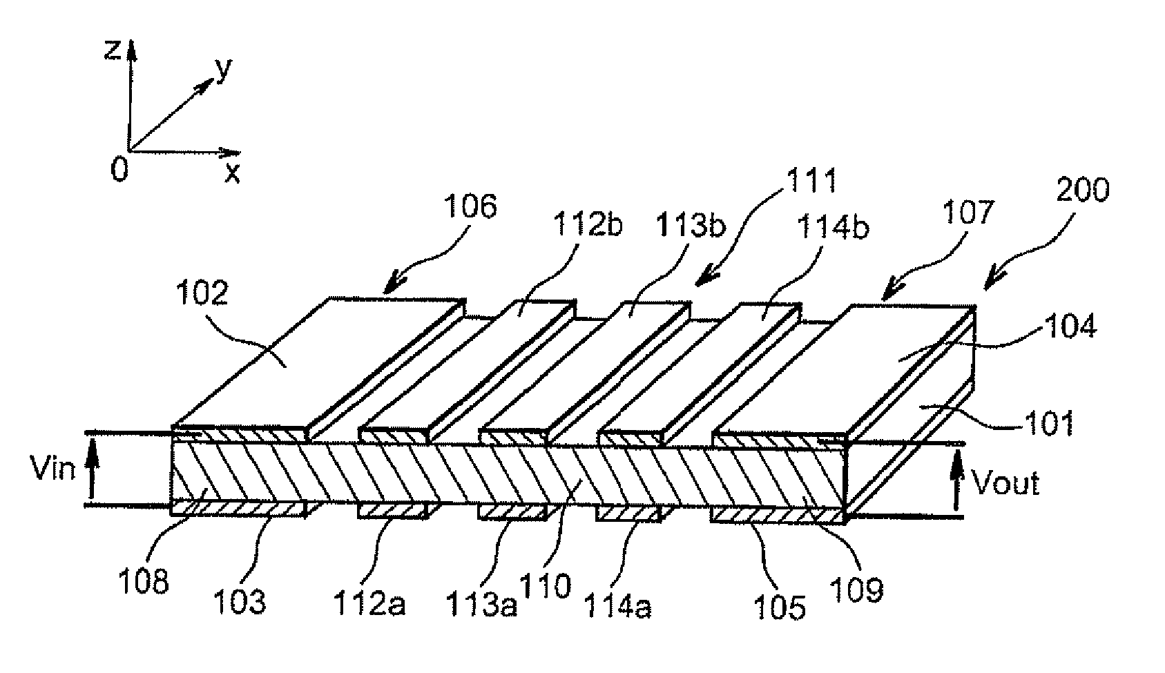
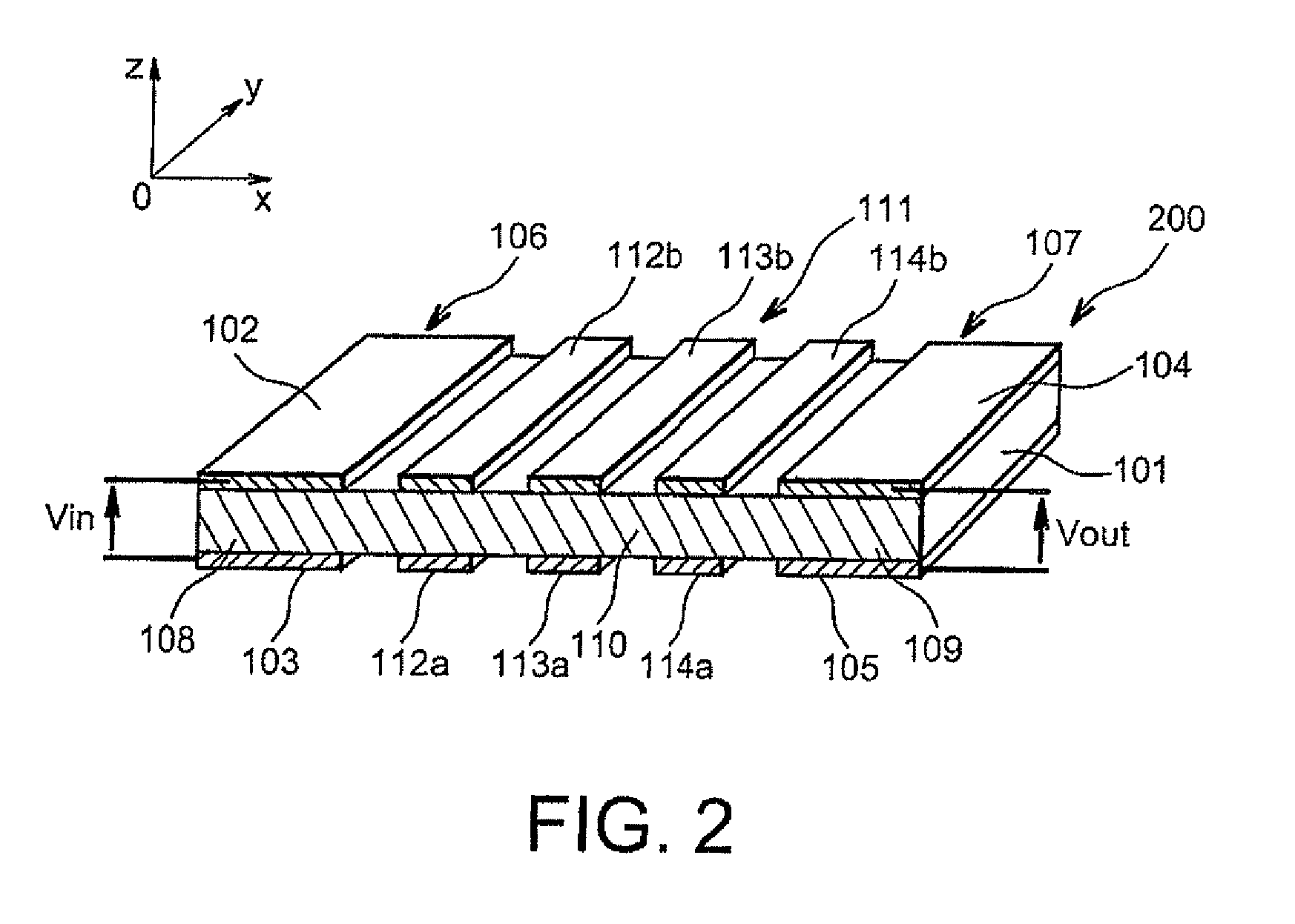
[0058]In this second embodiment, the coupled Lamb wave resonators filter 200 is made to obtain a narrow passband at the output centered around a central frequency equal to about

[0059]fc=cλc.

In this case, the length of the layer of resonant material 101 is equal to about

[0060]11⁢λc4.

As in the first embodiment, the length of each resonator 106, 107 is about

[0061]λc2.

Therefore, in this case the length of the portion of resonant material 110 of the periodic lattice 111 is equal to about

[0062]7⁢λc4.

[0063]The periodic lattice 111 comprises a first pair of metal areas 112a, 112b arranged above and below the portion of resonant material 110, and are vertically aligned with each other. These metal areas 112a, 112b are arranged at a distance of about

[0064]λc4

from the first resonator 106. A second pair of metal areas 113a, 113b, similar to the first pair of metal areas 112a, 112b, is arranged at a distance of about

[0065]λc4

from the first pair of metal areas 112a, 112b. Finally, a third pair of...

third embodiment

[0086]It is also possible to use periodic lattices to acoustically couple more than two resonators. FIG. 3 shows a coupled Lamb wave resonator 300 according to a

[0087]This filter 300 comprises a first Lamb wave resonator 106 coupled to a second Lamb wave resonator 107 by a first periodic lattice 111. These three elements may be similar to the elements shown in FIG. 2. The filter 300 also comprises a third Lamb wave resonator 121 comprising a resonant layer 122 arranged between two electrodes 123, 124 in a manner similar to the two other resonators 106, 107. The second and third resonators 107 and 121 are acoustically coupled through a second periodic lattice 125, for example similar to the first periodic lattice 111. The second periodic lattice 125 comprises a layer of resonant material 126 arranged between a plurality of pairs of metal areas 127 to 129 arranged on the layer 126 in a manner similar to the metal areas 112 to 114 on the layer 110.

[0088]In this embodiment, the layers 1...


PUM

PropertyMeasurementUnit
frequenciesaaaaaaaaaa
frequencyaaaaaaaaaa

Abstract

A coupled Lamb wave resonator filter includes first and second Lamb wave resonators. The first Lamb wave resonator includes a first resonant layer, and first and second electrodes on opposite sides of the first resonant layer. The second Lamb wave resonator includes a second resonant layer, and third and fourth electrodes on opposite sides of the second resonant layer. One of the sides of the first resonant layer belongs to a plane parallel to a plane corresponding to one of the sides of the second resonant layer. Both planes pass through the third and fourth electrodes of the second Lamb wave resonator. A periodic lattice acoustically couples the first and second resonant layers.

Description

FIELD OF THE INVENTION[0001]The invention relates to filters, and more particularly, to coupled resonator filters. Coupled resonator filters may be used in multistandard emission and / or reception architectures, including portable communication devices that can perform mobile communications according to several standards (GSM, GPRS, UMTS, WLAN, etc.) and / or different telephone standards of the 2 G, 2.5 G, 3 G type. Coupled resonator filters may also be used to filter channels or to filter intermediate frequencies.BACKGROUND OF THE INVENTION[0002]Coupled resonator filters can be made using bent or twisted electromechanical resonators, or electromechanical resonators with bulk waves. In this type of filter, the dimensions of the resonant elements need to decrease as the resonant frequency increases. This causes manufacturing, cost and reliability problems. Furthermore, the input / output impedances of these filters are very high (about several kohms) due to the nature of the detection ma...

Claims


Application Information

Patent Timeline
Patent Type & Authority Patents(United States)
IPC IPC(8): H03H9/54H03H9/56
CPCH03H9/02228Y10T29/42
Inventor VOLATIER, ALEXANDREANCEY, PASCALDUBUS, BERTRAND
Owner STMICROELECTRONICS SRL
Why Eureka
Try Eureka