Tire pressure management system valve integrity verification method

a technology of tire pressure management system and integrity verification, which is applied in the direction of functional valve types, transportation and packaging, liquid handling, etc., can solve the problems of ultimate failure of tire pair on one end of axle, loss of vehicle control, and system failures with potentially costly and/or dangerous consequences

Inactive Publication Date: 2005-05-17
DANA HEAVY VEHICLE SYSTEMS GROUP LLC
View PDF53 Cites 55 Cited by
  • Summary
  • Abstract
  • Description
  • Claims
  • Application Information

AI Technical Summary

Benefits of technology

[0004]The invention provides a method of verifying the integrity of a valve in service in a tire pressure management system. The method of verifying valve integrity of a valve interposed between a tire and conduit assemblies for conducting fluid to and/or from the tire in a tire ma

Problems solved by technology

Despite the advances gained in tire pressure management systems, while in service, system failures can develop with potentially costly and/or dangerous consequences.
Failure of wheel valve assembly 30 could lead to rapid deflation of an assoc

Method used


Image

  • Tire pressure management system valve integrity verification method
  • Tire pressure management system valve integrity verification method
  • Tire pressure management system valve integrity verification method

Examples


Embodiment Construction

[0011]The invention is an apparatus for and a method of verifying the integrity of a valve. Specifically, the invention verifies the, capacity of a valve to effectively prevent fluid from passing therethrough, such as, for example, air escaping from a tire when a tire pressure management system is not inflating or deflating vehicle tires.

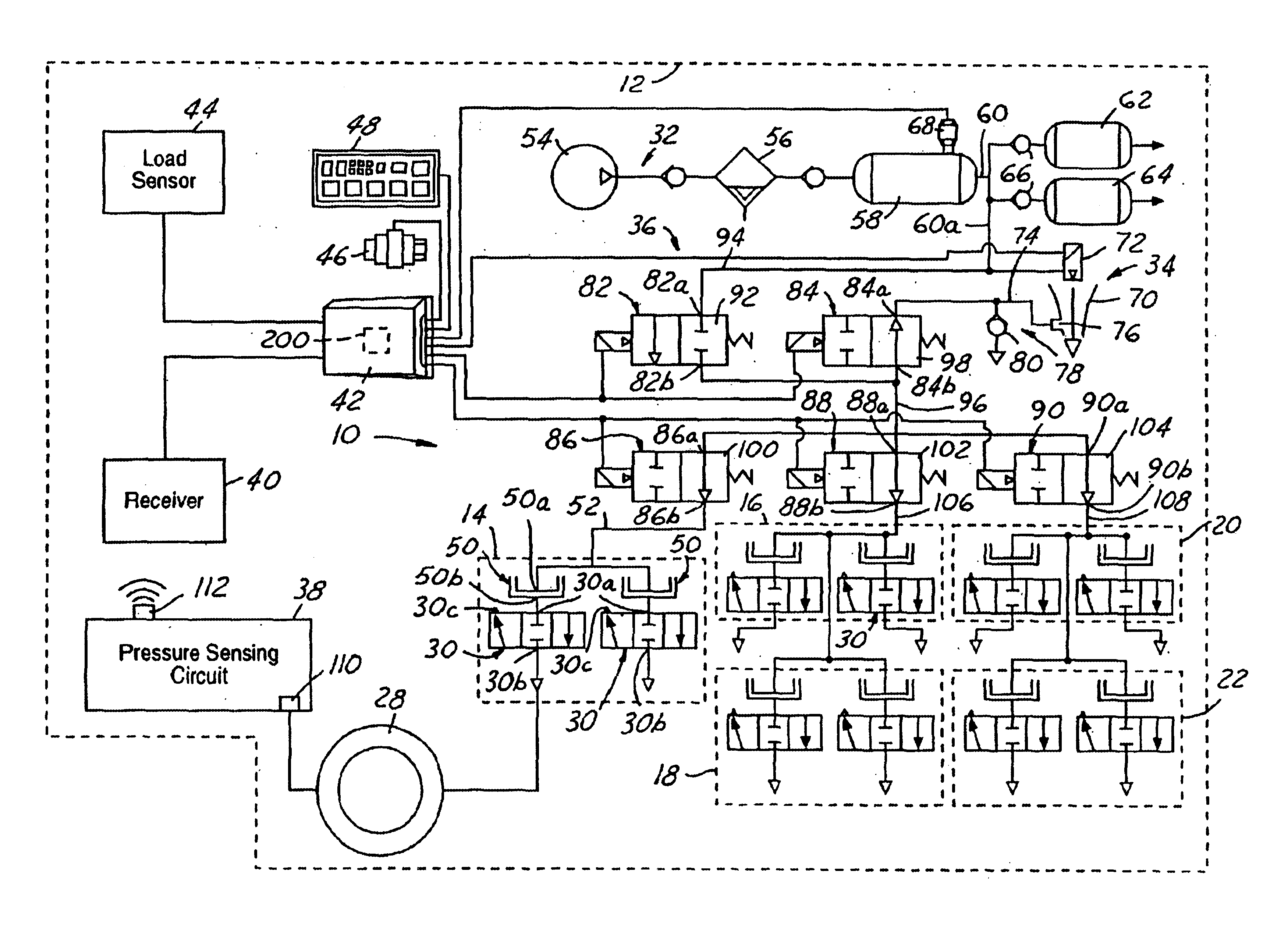
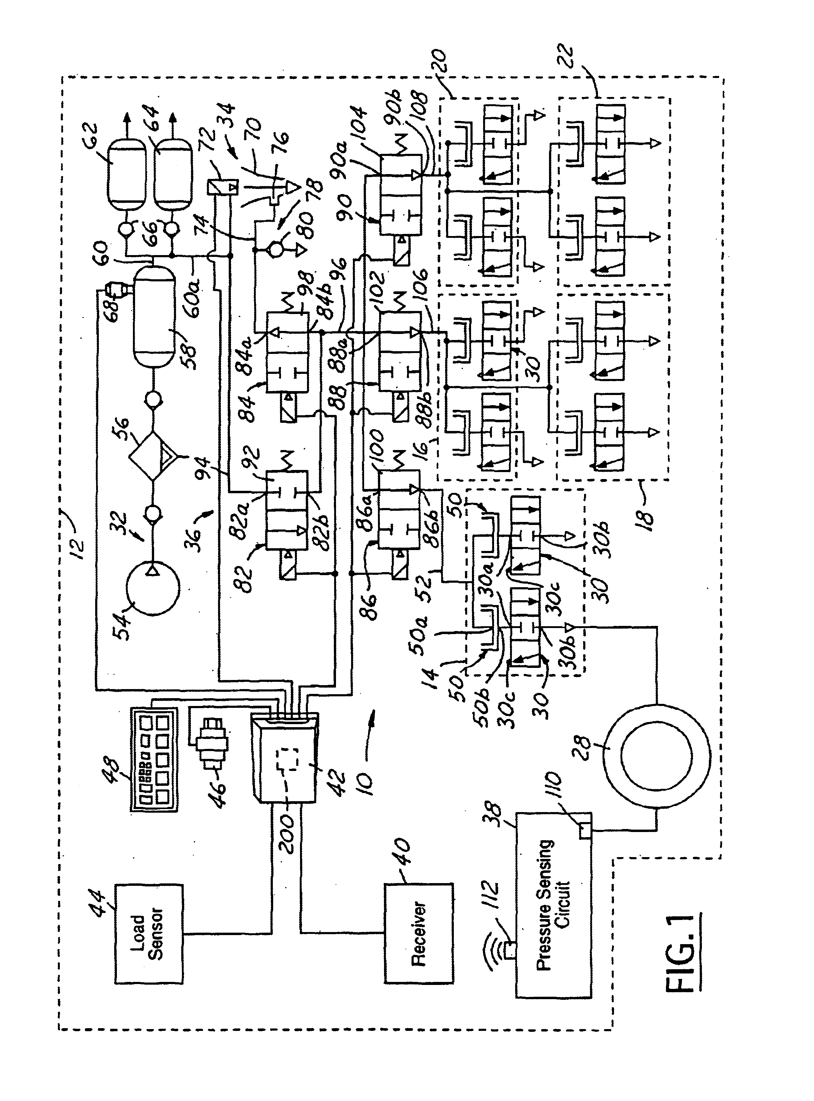
[0012]FIG. 1 shows a tire pressure management system 10 for a vehicle 12 for describing, but not limiting applicability of the invention. Vehicle 12 may be, but is not limited to being a tractor-trailer. The system may be used in connection with a wide variety of vehicles, including automobiles.

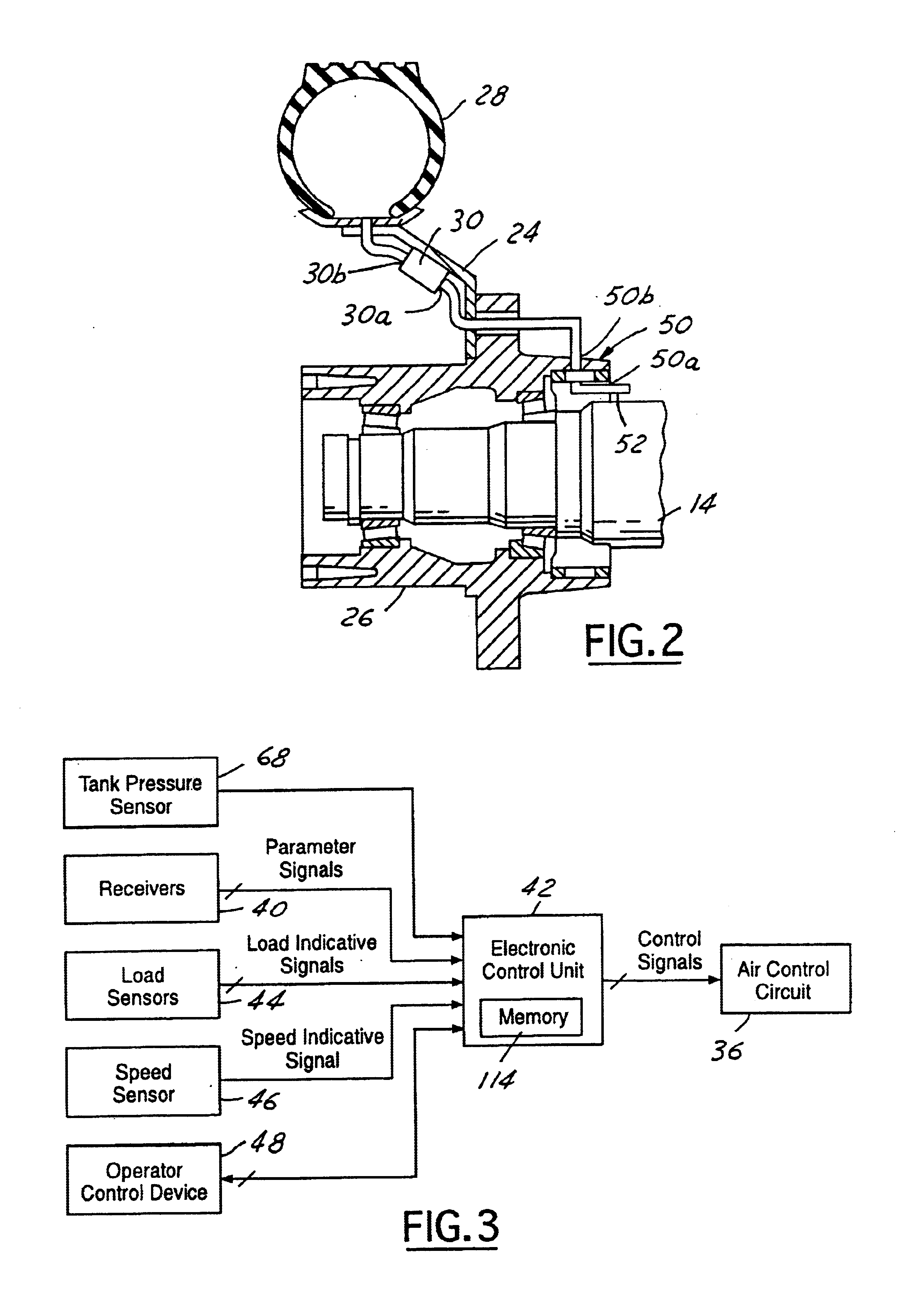
[0013]Vehicle 12 may include a plurality of axles, including a steer axle 14, a tandem axle assembly having drive axles 16, 18 and another tandem axle assembly having trailer axles 20, 22. As shown in greater detail in FIG. 2, each axle, such as drive axle 14, may include wheels 24 affixed to wheel hubs 26 disposed at each outboard end of the axle and rotatio...


PUM


Abstract

A method of verifying the integrity of a valve in service in a tire pressure management system is disclosed. The method of verifying valve integrity of a valve interposed between a tire and conduit assemblies for conducting fluid to and/or from the tire in a tire maintenance system includes closing the valve for prohibiting fluid flow into the conduit assemblies in fluid communication with the valve and monitoring the pressure of fluid in the conduit assemblies in fluid communication with the valve for ascertaining a pressure increase therein.

Description

BACKGROUND OF THE INVENTION[0001]Conventional tire pressure management systems typically have central tire inflation systems (CTI systems), also known as on-board inflation systems and traction systems. These tire pressure management systems are well known, as may be seen by reference to the following U.S. Pat. Nos.: 5,516,379; 5,313,995; 5,273,064; 5,253,687; 5,180,456; 5,179,981; 5,174,839; 5,121,774; 4,924,926; 4,922,946; 4,917,163; 4,893,664; 4,883,106; 4,883,105; 4,825,925; 4,782,879; 4,754,792; 4,724,879; 4,678,017; 4,640,331; and 4,619,303. The entire disclosure of each of these patents is incorporated herein.[0002]Generally, tire pressure management systems employ a pneumatically controlled wheel valve that is affixed to each vehicle wheel assembly for controlling tire pressure in response to pressure signals from a fluid control circuit. The fluid control circuit is connected to each wheel valve via a rotary seal assembly associated with each wheel valve. Tire pressure is m...

Claims


Application Information

Patent Timeline
IPC IPC(8): B60C23/00
CPCB60C23/04B60C23/003B60C23/00318B60C23/00354B60C23/00372Y10T137/36Y10T137/3631
Inventor CLAUSSEN, STEPHEN P.STACER, DARYL J.
Owner DANA HEAVY VEHICLE SYSTEMS GROUP LLC
Why Eureka
Try Eureka