Light wave distance-measuring system

a technology of distance measurement and light wave, which is applied in the direction of distance measurement, instruments, and using reradiation, etc., can solve the problems of high manufacturing cost of the system, measurement cannot be done, and light cannot be received

Inactive Publication Date: 2005-05-17
KK TOPCON
View PDF7 Cites 35 Cited by
  • Summary
  • Abstract
  • Description
  • Claims
  • Application Information

AI Technical Summary

Benefits of technology

[0008]It is an object of the present invention to provide a light wave distance-measuring system, in which an optical axis of an outgoing light is consistent with an optical axis of a returning light, sufficient amount of receiving light can be obtained for measurement at near distance as well as for measurement at long distance, and a distance can be measured in stable manner.

Problems solved by technology

However, light cannot be received when the image-forming position is deviated from the optical axis, and measurement cannot be made.
When the photodetection unit is designed as movable, a structure with high mechanical accuracy is required, and this leads to higher manufacturing cost of the system.
When the optical auxiliary member is provided, the amount of receiving light is not sufficient, and a range of measurement is limited to a fixed range.
However, the reflection light of the portion consistent with the optical axis is blocked by the reflection mirror.
Because the image-forming position is deviated in the backward direction, there is such problem that the light is not received on the photodetection unit, and measurement cannot be made.
In case of coaxial arrangement, the same means can be applied as in the case of parallel arrangement, but the range of measurement is limited to a fixed range.

Method used


Image

  • Light wave distance-measuring system
  • Light wave distance-measuring system
  • Light wave distance-measuring system

Examples


first embodiment

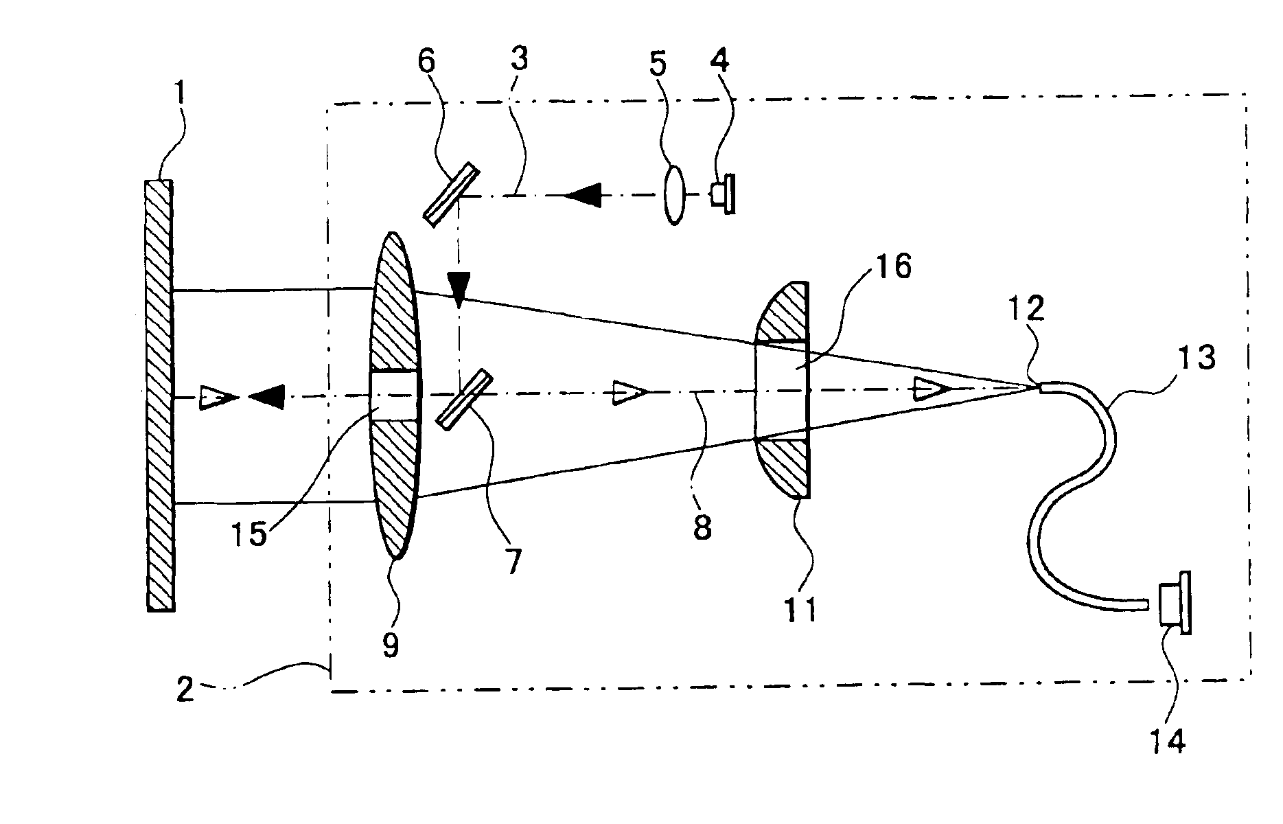
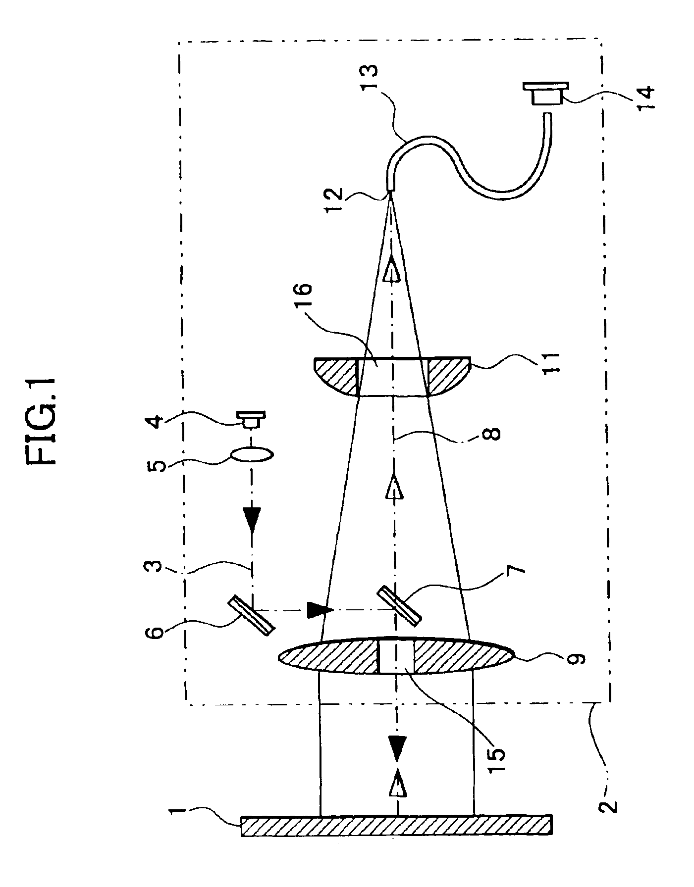
[0018]FIG. 1 shows the present invention. In the figure, reference numeral 1 denotes an object reflector representing a commonly used material such as a wall, which is to be an object for measurement, and 2 represents a light wave distance-measuring system.

[0019]Now, description will be given on the light wave distance-measuring system 2.

[0020]On an optical axis 3 of an outgoing light beam, a light source 4 for emitting a visible laser beam, a condenser lens 5, and a first mirror 6 are arranged. A second mirror 7 is arranged at a position opposite to the first mirror 6. The laser beam emitted from the light source 4 is turned to a parallel beam by the condenser lens 5. After being reflected by the first mirror 6 and the second mirror 7, the laser beam passes through an aperture 15 of a light receiving lens 9 and is projected toward the object reflector 1. The condenser lens 5, the first mirror 6, the second mirror 7, etc. make up together a projection optical system.

[0021]On an opti...

third embodiment

[0041]FIG. 5 shows the invention.

[0042]In the third embodiment, a doughnut-like cone prism 18 is used as the light converging optical member, which has the approximate same function as the perforated light converging lens 11. When the cone prism 18 is used, the reflection light can be converged in the same manner as above. The cone prism 18 has a wedge-like cross-section, and has a form of a doughnut continuously arranged in a circular form.

[0043]FIG. 6 shows a variation of the third embodiment, and it represents a perforated light converging optical member 19, which comprises two types of wedge prisms 19a and 19b with different vertical angles. In this light converging optical member 19, a total circumference is divided into 4 equal portions, and opposed pairs are designed as wedge prisms 19a and 19a as well as wedge prisms 19b and 19b respectively having the same vertical angle. In this variation of the third embodiment, the wedge prism 19a and the wedge prism 19b have different l...


PUM


Abstract

A light wave distance-measuring system, comprising a projection optical system having an optical axis of outgoing light and for projecting a measuring light, and a photodetection optical system having an optical axis of a returning light and for receiving a reflection light, wherein the photodetection optical system comprises a light receiving lens for receiving and for converging the reflection light, a light receiving surface where the reflection light enters, and a ring-like perforated multi-focal optical member arranged between the light receiving surface and the light receiving lens and for converging the light to the light receiving surface.

Description

BACKGROUND OF THE INVENTION[0001]The present invention relates to a portable type light wave distance-measuring system of handy design. In particular, the invention relates to a light wave distance-measuring system for measuring a distance up to short-distance range by receiving a retroreflection diffusion light from a commonly used material such as a wall.[0002]In recent years, a portable type distance-measuring system has been produced and marketed, which is provided with light wave distance-measuring function of non-prism type without using a reflection prism.[0003]For instance, a portable type distance-measuring system is disclosed in Japanese Patent Gazette No.JP-A-2000-187076. In this system, collimation is not performed as in a surveying instrument of total station type. Using a distance-measuring visible light as a pointer, an arbitrary measuring point is specified, and a distance is measured. This system comprises a projection optical system for projecting a distance-measur...

Claims


Application Information

Patent Timeline
Patent Type & Authority Patents(United States)
IPC IPC(8): G01C3/08G02B3/10G02B5/04G02B3/06G02B3/02G01S7/481G01S17/36G01S17/00G01S7/48G01S7/491G01C3/06G01S7/4915G01S17/08
CPCG01C3/08G01S7/4812G01S7/4915G02B3/06G02B3/10G02B5/04G01S7/491G01S17/36
Inventor ISHINABE, IKUOKODAIRA, JUN-ICHI
Owner KK TOPCON
Why Eureka
Try Eureka