Projection screen and method for manufacturing the same

a technology of projection screen and projection screen, which is applied in the field of projection screen, can solve the problems of difficult to increase the contrast of the projection screen in a bright environment, the external light cannot be suppressed, and the projection screen b>100/b> cannot achieve satisfactory viewing characteristics, etc., and achieves simple structure, reduced viewing characteristics, and increased viewing angles.

Inactive Publication Date: 2005-05-17
SONY CORP
View PDF11 Cites 47 Cited by
  • Summary
  • Abstract
  • Description
  • Claims
  • Application Information

AI Technical Summary

Benefits of technology

[0012]Accordingly, an object of the present invention is to provide a projection screen on which distinct images can be formed and which exhibits enhanced viewing characteristics, and to provide a method for manufacturing the same.
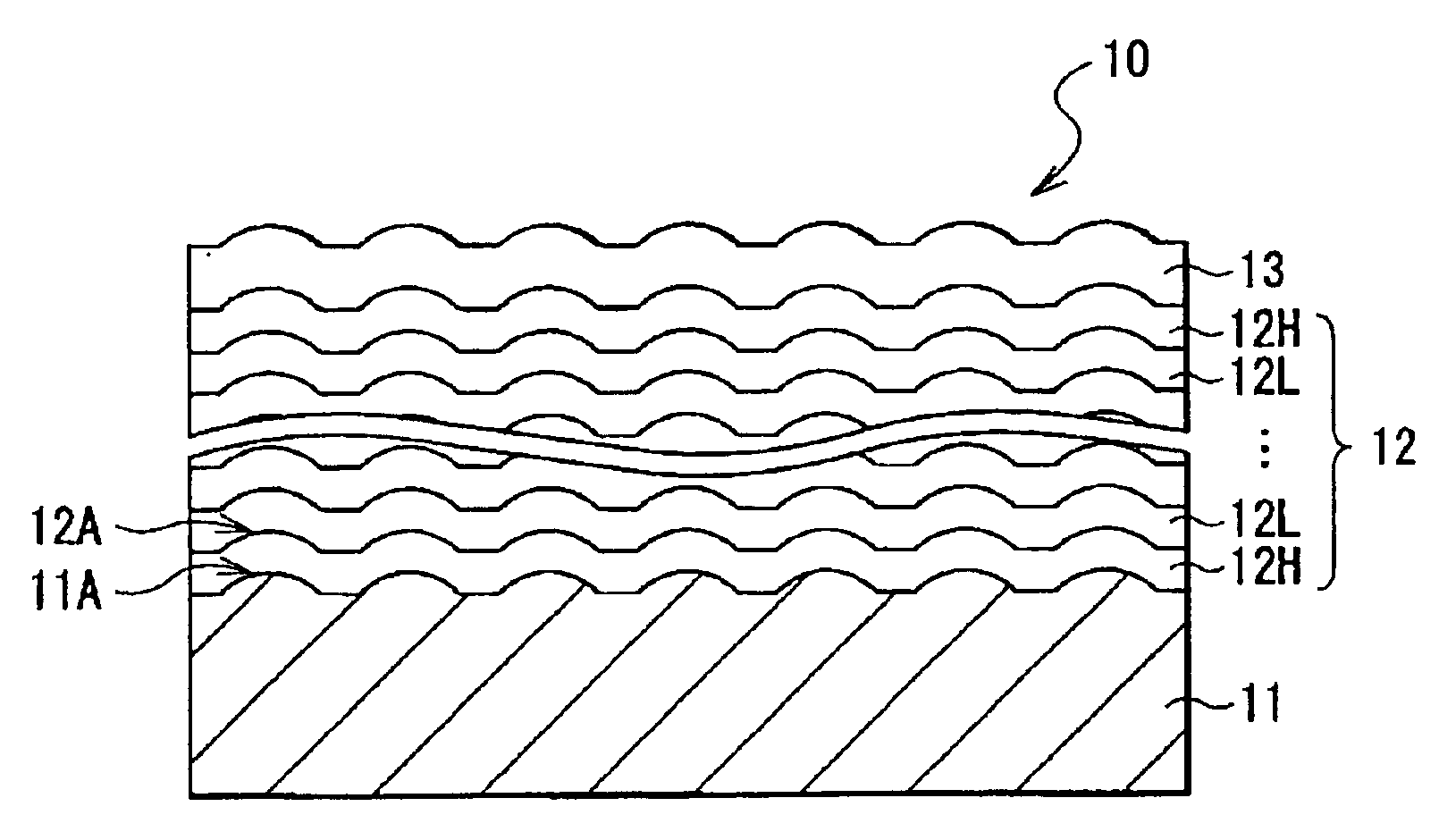
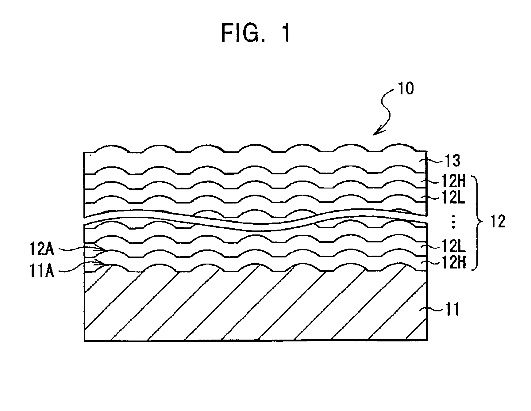
[0014]By providing the light diffusion control portion having the plurality of convex or concave portions on the surface of the substrate and further providing the convex or concave portions having the same shape as that of the convex or concave portions of the light diffusion control portion to the optical thin film, light rays incident on the optical thin film have predetermined incident angles. Therefore, a predetermined percentage of the light in the specific wavelength band is diffuse-reflected at angles twice the incident angles. Thus the viewing angle of the screen is increased. Consequently, distinct images can be formed regardless of projection environment, and viewing characteristics can be enhanced.
[0016]By forming the light diffusion control portion having the plurality of convex or concave portions on the surface of the substrate and further forming the optical thin film so as to have convex or concave portions having the same shape as that of the convex or concave portions of the light diffusion control portion, light rays incident on the optical thin film have incident angles at the convex or concave portions of the optical thin film. Therefore, a predetermined percentage of the light in the specific wavelength band is diffuse-reflected at angles twice the incident angles from the optical thin film. Thus, the viewing angle of the screen is increased.
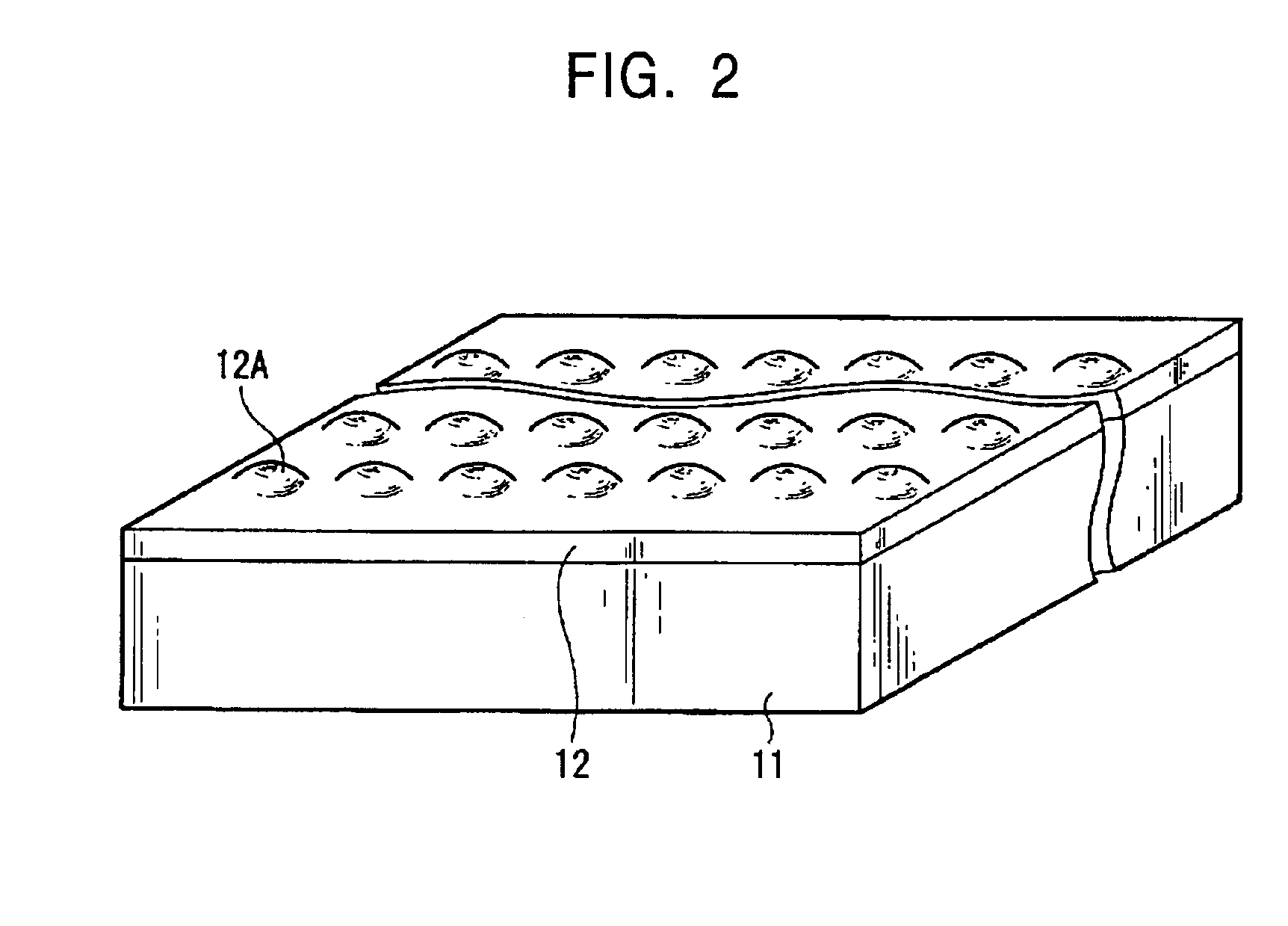
[0017]Also, since the convex or concave portions are provided on the surface of the substrate to form the light diffusion control portion, a projection screen having a simple structure can be achieved by forming the optical thin film so as to have the convex or concave portions having the same shape as that of the convex or concave portions of the light diffusion control portion. As a result, the variation of optical characteristics, viewing characteristics, and other characteristics can be reduced, and, accordingly, reliability is increased. Also, manufacturing cost can be reduced.
[0018]The light diffusion control portion may be designed according to an optical simulation so that the convex or concave portions determine the angle of the reflection from the optical thin film. Thus, the range of reflection angle can appropriately be set, and, consequently, viewing characteristics can be controlled. Thus, viewing characteristics can further be enhanced.
[0019]The light diffusion control portion may include a plurality of spherical beads having a predetermined diameter and a bead-fixing layer filling the spaces between the beads to fix the beads. The thickness of the bead-fixing layer may be set with respect to the diameter of the beads, thereby determining the angles of reflection from the optical thin film. By setting the angles of the reflection from the optical thin film depending on the thickness of the bead-fixing layer, the range of reflection angle can appropriately be set, and, consequently, viewing characteristics can be controlled. Thus, viewing characteristics can further be enhanced.

Problems solved by technology

In front projectors using such a reflective projection screen, unfortunately, the reflection of external light cannot be suppressed by, for example, using a neutral density (ND) filter, in contrast to self-luminescent displays and rear projectors.
In particular, it is difficult to increase the contrast on the projection screen in a bright environment.
However, since the light diffusion layer 113 provides a viewing angle as small as 20°, the projection screen 100 cannot achieve satisfactory viewing characteristics.

Method used


Image

  • Projection screen and method for manufacturing the same
  • Projection screen and method for manufacturing the same
  • Projection screen and method for manufacturing the same

Examples


modification 1

[0052

[0053]Although, in the foregoing embodiment, the plurality of convex portions 11A are provided on the surface of the substrate 11 to control diffuse reflection, concave portions 31A may be formed on the surface of a substrate 31, instead of the convex portions 11A, as shown in FIGS. 5 and 6. FIG. 6 does not show the parts above an optical thin film 32 for convenience.

[0054]A projection screen 30 including such a substrate 31 is manufactured according to the following. The substrate 31 is prepared from a macromolecular material containing a black paint as in the foregoing embodiment. The surface of the substrate 31 is subjected to, for example, embossing to form the concave portions 31A. Each concave portion 31A may have a curvature radius r of several micrometers to several millimeters. The shape, curvature radius r, arrangement, area ratio, surface properties, and the like of the concave portions 31A are designed according to, for example, an optical simulation. Since the conc...

modification 2

[0057

[0058]Although, in the foregoing embodiment, the plurality of convex portions 11A serving as a light diffusion control portion are formed on the surface of the substrate 11 by, for example, embossing, a light diffusion control portion 42 may be provided on a substrate 41, as shown in FIG. 8. The light diffusion control portion 42 is essentially composed of a plurality of beads 43 and a bead-fixing layer 44 filling between the beads to fix the beads 43.

[0059]The beads 43 are formed of glass or a transparent material, such as a polymer, in a spherical shape having a uniform diameter d of, for example, several micrometers to several millimeters. The bead-fixing layer 44 is formed of a resin or the like to fix the beads, filling the spaces between the beads 43. The thickness of the bead-fixing layer 44 is, for example, smaller than the diameter d of the beads. Thus, convex portions 42A similar to the convex portions 11A of the foregoing embodiment can be formed on the surface of th...


PUM


Abstract

A projection screen includes a plurality of convex portions serving as a light diffusion control portion, on the surface of a substrate. An optical thin film overlies the substrate and has convex portions having the same shape as that of the convex portions of the substrate. When external light enters the optical thin film with light in three primary color wavelength bands, the optical thin film reflects only the light in the three color wavelength bands and absorbs at least visible light of the external light. When light in the three primary color wavelength bands perpendicularly enters the optical thin film, the rays of the light have incident angles at the convex portions of the optical thin film and diffuse-reflected at angles twice the incident angles. Thus, a predetermined percentage of the light is diffused to increase the viewing angle of the screen.

Description

BACKGROUND OF THE INVENTION[0001]1. Field of the Invention[0002]The present invention relates to projection screens on which images are displayed by receiving light from a light source. In particular, the present invention relates to a reflective projection screen and a method for manufacturing the same.[0003]2. Description of the Related Art[0004]Overhead projectors and slide projectors have widely been used for showing materials in meetings and the like. Also, the use of video projectors and animation film projectors is spreading to ordinary households. In these projectors, light from a light source is spatially modulated to imaging light by a light valve, and the image light is projected onto a screen through an illumination optical system, such as a lens.[0005]Some of this type of projectors can display color images and in which a lamp for emitting white light including three primary colors, which are red (R), green (G), and blue (B), is used as the light source and a transmissi...

Claims


Application Information

Patent Timeline
Patent Type & Authority Patents(United States)
IPC IPC(8): G03B21/56G03B21/60G02B5/02G02B5/26G02B5/28
CPCG03B21/56G03B21/60
Inventor OHSAKO, JUNICHIKAKINUMA, MASAYASUCHUBACHI, HIDEYAHAYASHI, HIROSHI
Owner SONY CORP
Why Eureka
Try Eureka