Article production method
a production method and article technology, applied in the direction of chemistry apparatus and processes, manufacturing tools, transportation and packaging, etc., can solve the problems of reducing the capacity utilization rate and occurrence of similar problems with articles other than worn articles
- Summary
- Abstract
- Description
- Claims
- Application Information
AI Technical Summary
Benefits of technology
Problems solved by technology
Method used
Image
Examples
first embodiment
[0064]FIG. 5 is a diagram illustrating an example of a production apparatus for producing an article. Specifically, the production apparatus is capable of producing a diaper, which is a type of worn article. The production apparatus includes at least one rotating member having a machining section.
[0065]A press unit 3 includes a press roll 3a and an anvil roll 3b. The press unit 3 illustrated in FIG. 5 presses a continuous mat Wm, and thus does not normally have a protrusion. However, in a case where a particular position of the continuous mat Wm is pressed or where the position at which it is pressed changes according to the size, the press roll 3a acting as a rotating member may be controlled based on the principle of the present invention. The mat Wm capable of absorbing a liquid that is passed to the press unit 3 is formed to a predetermined thickness by the press roll 3a. Note that it is preferred that the circumferential velocity of the anvil roll 3b is generally the same as th...
second embodiment
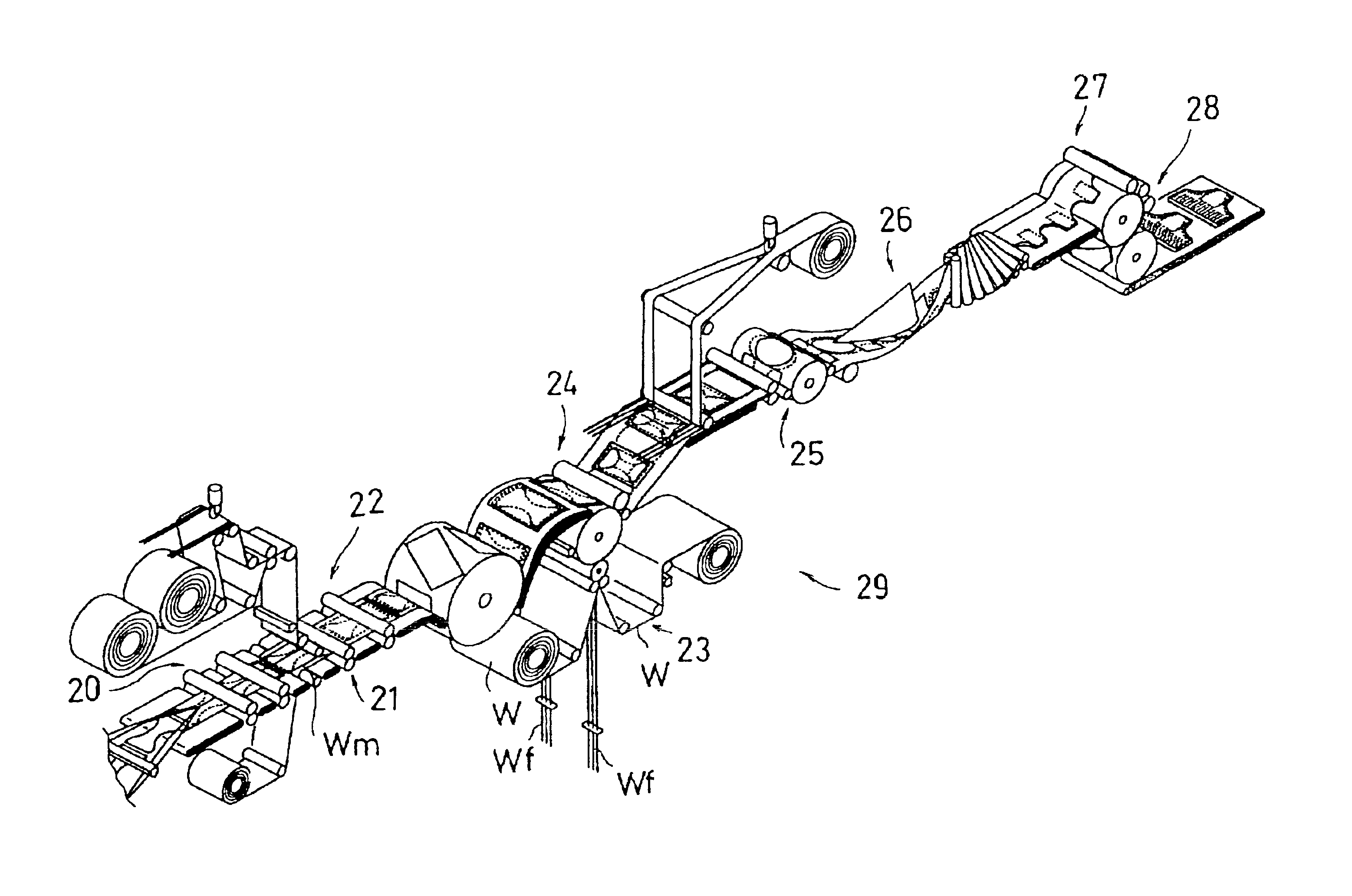
[0112]The second embodiment will now be described. FIG. 9 is a diagram illustrating an example of a production apparatus for producing an article. Specifically, a production apparatus 29 is capable of producing a pants-type diaper, which is a type of a worn article.
[0113]The production apparatus 29 includes a first cutter unit 20 for cutting the mat Wm, a first seal unit 21 for sealing an end of a combined member obtained by combining a cut-off mat with another web placed thereon, a second cutter unit 22 for cutting along a line between the sealed portions, and a guide unit 23 for guiding and introducing the elastic member Wf between the webs W.
[0114]The production apparatus 29 further includes a second seal unit 24 for sealing the web W, onto which the elastic member Wf has been introduced, and the combined member together, a trim cutter unit 25 for opening a leg hole, etc., in the sealed web, a folding unit 26 for folding the web with the hole opened therein, a third seal unit 27 ...
third embodiment
[0125]The third embodiment will now be described. FIG. 16 is a diagram illustrating an example of a production apparatus for producing an article.
[0126]An apparatus 130 includes a guide section 134 for guiding the elastic member Wf between webs W1 and W2, a nip roll 131 and the assembly drum 8 for sandwiching and adhering the elastic member Wf between the webs W1and W2, and a re-pitching drum 132 for receiving the mats Wm from a transfer section 133 and changing the interval between the mats Wm. On the assembly drum 8, the mat Wm is placed on the webs W1 and W2, in which the elastic member Wf has been placed in a predetermined shape. An adhesive is applied intermittently or continuously on at least one of the webs W1 and W2. Note that the nip roll 131 has a diameter that is smaller than that of the assembly drum 8 holding the web W2 thereon. Moreover, if the nip roll 131 has a peelability to the adhesive, it is possible to omit the web W1, thereby reducing the cost of the article. M...
PUM
| Property | Measurement | Unit |
|---|---|---|
| radius | aaaaa | aaaaa |
| velocity | aaaaa | aaaaa |
| velocity | aaaaa | aaaaa |
Abstract
Description
Claims
Application Information
 - R&D
- Intellectual Property
- Life Sciences
- Materials
- Tech Scout
- Unparalleled Data Quality
- Higher Quality Content
- 60% Fewer Hallucinations
Browse by: Latest US Patents, China's latest patents, Technical Efficacy Thesaurus, Application Domain, Technology Topic, Popular Technical Reports.
© 2025 PatSnap. All rights reserved.Legal|Privacy policy|Modern Slavery Act Transparency Statement|Sitemap|About US| Contact US: help@patsnap.com


